how to modify a circuit to a grounded switch from a positive switched circuit?

Thread Starter

sternpirate

Joined Dec 10, 2015
25
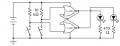
I built this circuit https://www.allaboutcircuits.com/textbook/experiments/chpt-7/nor-gate-s-r-latch/ on perfbord and while it works perfectly the project I need it in has a switch permanently coupled to ground. I'd rather not rip up the pcb to isolate the switch from ground. So i'm scratching my head here as it seems to require different resistor values since the flipflops must remain pulled to ground. all i can think of is to buffer each switch with a not gate but that would add too much complexity.
 

Reloadron

Joined Jan 15, 2015
7,517
Not sure what you are trying to do but would using an OR gate rather than a NOR gate work for you? You have a CD 4001 NOR gate which could be replaved by a CD 4071.

CD4001
INPUT OUTPUT
A B A NOR B
0 0 1
0 1 0
1 0 0
1 1 0

CD4071
INPUT OUTPUT
A B A OR B
0 0 0
0 1 1
1 0 1
1 1 1

The resistors in the linked circuit are there to make sure the CD 4001 Inputs are held low and not floating until a logic high is applied when the switches are closed. The truth tables for both chips are shown above. Again, I am not quite sure what you are after and possibly another member will have a better solution.

Ron
 

Thread Starter

sternpirate

Joined Dec 10, 2015
25
Not sure what you are trying to do but would using an OR gate rather than a NOR gate work for you? You have a CD 4001 NOR gate which could be replaved by a CD 4071.

CD4001
INPUT OUTPUT
A B A NOR B
0 0 1
0 1 0
1 0 0
1 1 0

CD4071
INPUT OUTPUT
A B A OR B
0 0 0
0 1 1
1 0 1
1 1 1

The resistors in the linked circuit are there to make sure the CD 4001 Inputs are held low and not floating until a logic high is applied when the switches are closed. The truth tables for both chips are shown above. Again, I am not quite sure what you are after and possibly another member will have a better solution.

Ron
Thanks for responding. It actually doesn't matter which chip I use for this. The purpose is for an experiment in switch debouncing. It does not matter to me that it is needlessly complicated.

You can see in the attached image what I want. I have relocated the switch to ground. Obviously this is not workable as the short to ground through the switch could damage the ic.
 

Attachments

Reloadron

Joined Jan 15, 2015
7,517
As drawn you will not damage the IC. As drawn the resistors are serving as pullup rather than pulldown on the gate inputs. closing either switch will place the gate inputs at a logic low. That will not hurt the chip and is pretty common. The inputs are held high through the 10K resistors, closing either or both switches will place a low on the gate inputs. Nothing bad will happen. With both switches open the inputs will be 1 and closing a switch brings the input(s) to 0. Both switches closed will be 0 and 0 on the inputs resulting in a 1 at the output, just like the truth table.

Ron
 

Thread Starter

sternpirate

Joined Dec 10, 2015
25
Thanks, that's all I was after. There is a warning that CMOS chip is static sensitive. Could it break down over time from switching spark jumps? I could buffer the switches to protect it but it it necessary?
 
Last edited:
Top