How to measure the temperature in induction heater

Thread Starter

mohan.n2293

Joined Jan 23, 2017
60
Hi All,

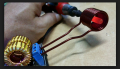
I have designed a small induction heater with 18w of input power input is DC 12V and 3A.
I have used a copper to make a working coil and small iron core is my heating peice.
Iron dimension :
Inner Diameter : 7.5mm
Outer Diameter : 8mm
Length of core : 12mm

Here im having big issue in controlng the temperature ,i need a suggestion that how can i detect the temperature range and control to constant temperature.

I have tried with IR based sensor but it dint work it was showing 105 C when coil heated to 350C.
Please anyone suggest me a temperature sensor that should of contact type and it shouldn't gets heat for magnetic field.
 

Thread Starter

mohan.n2293

Joined Jan 23, 2017
60
Would it be possible to use Tempilaq® Indicating Liquids. If all of your parts are uniform once you establish a dwell time for the heater the parts should all heat uniform in the same time frame. You need to better explain what your goal is. Also when using IR sensing have you considered the Principles of Non-Contact Temperature Measurement especially the emissivity factor of the alloy?

Thanks for your Replay,

But in my case please find the my setup in the image its very difficult to sens using IR sensor
 

Attachments

Janis59

Joined Aug 21, 2017
1,849
Depends on a demands and pocket.
All kind of therocouple will evaporate at first second.
Optical methods will be dependant on blackness factor what is unstable and changes even not only from substance to substance, but from temperature to temperature. Thus, if the +/- 100C is acceptable, then infrared thermometry
Other is red-hot wire method, to measure the amperes and adjust while naked eye says both are similar. The same +/- 100C.
The awhile first method on the Planet capable to measure that temp within few grade accuracy in no respect what the material is made from, is the Belorussian Acad of Sci ""Mass and Heat Transfer Institute"" (Minsk) method and respectively thermometer, giving +/- 0,5% of reading plus 1/2 of centigrade uncertainty. But the price is written by 5 digits.
The whole idea is measure NOT a Plancks whole integral power emitted in certain angle as it is done by ordinary IR meter, but measure it at two different narrow wavelengths afterwards computer calculating the Wien`s maximum placement, respectively temperature. Apparatus is specially designed for use in induction melting owen.
The blackness factor they get rid of, using the high-temp ampulae in the melted liquid, thus in no respect of melted material the meter is always looking on the same material and place.
By the way, they are very opened about all people willing to buy it. Just write them.
 

neonjohn

Joined Mar 3, 2013
7
Greetings Mohan.

In general, there is no good method of measuring while heating.

Here are some of your problems. As you've discovered infrared sensors are so affected that they're worthless. In very large (multi-ton), I've seen multi-color IR pyrometers used to measure the crucible temperature. Two problems: When the heater is operating, the outside will always be hotter than the inner sections which do not get heated. Other problem is such devices cost thousands of $$$.

The RF energy only penetrates about 2 skin depths into the work. A good rule of thumb is that skin depth in mm = 400/frequency in Hz. The work that is deeper than that does not get heated inductively to any great extent. It's heated by thermal conductivity. So with a thicker piece, there will always be a temperature gradient through the material as long as the heat is turned on.

Given this, one should choose an operating frequency low enough that the penetration is about half the skin depth. (1 skin depth per side for tubing).

The best method we've come up with is to enclose the TC in a ceramic tube that will fit between the induction turns. Being perpendicular to the coil, essentially no heating occurs. The procedure is to heat the object for ever how long you think it will take, turn off the power, press the TC against the object and watch the temperature decline rapidly and then roughly stabilize, dropping only because of radiative and conduction losses. That roughly stabilized temperature is your setpoint. Tinker around with the heat interval until you achieve your setpoint.

This assumes constant power input to the load. This not easy to achieve. First the work coil heats up and increases its resistance. Copper has a fairly high thermal coefficient of electrical conductivity. If you reach the metal's Curie point (about 770 degc), the magnetic hysteresis in the steel, the primary heating mechanism in steel goes away, leaving only ohmic heating. The power absorption drops by about a third.

If you're doing this just for yourself, here's what I'd do. First thing is to come up with some metallurgical test that can be performed on the object to see if it has been heated enough (or too much). Determine what power input to the heater is necessary to achieve that goal, then lock down the knobs. Every so often pull a sample and perform the metallurgical QC test.

If you're trying to use the heater in the photo, toss it in the trash, sleazebay it or otherwise get rid of it. Practically everything is done wrong. No IGBT driver. Induction-heavy in the tank. Too many work coil turns, too close together. Won't survive over about 50 volts DC.

How do I know? That cheap Chicom heater like the one pictured is the one I designed about 15 years ago when I was first learning induction heating.

http://www.neon-john.com/Induction/Roy/Roy_Simple.png

I posted that design to my website but within 2 weeks had figured out everything I'd done wrong and posted an updated page. Here it is.

http://www.neon-john.com/Induction/Roy/Roy.htm

As you can see, I don't update my site very often :-( There are a few minor mods that should be made to improve the reliability of the heater. If anyone is interested in this, drop me a line. I'll redesign the the PCB and update the site.

Many things have changed since that page went up. Garett, my partner had an amicable split. I've come down with some sort of chronic disease - docs are leaning toward Parkinson's. The continuous fatigue from that has forced me to temporarily suspend the operation of Tnduction. Hopefully the docs will get this under control and we can re-open.

I've run that circuit up to 5kW and with the price of SOC FET transistors dropping like a rock, it should be good for much more. SOCs are the main battle tank of power FETs. I can't seem to kill one. For a current project I'm using a Cree device that rated at 1700 volts and 76 amps.

Incidentally, if you're looking at annealing ammo brass, Fluxeon now sells a ready-to-go unit called the Annie.

https://www.fluxeon.com/

You might want to take a look.

John DeArmond
Chief Engineer, Tnduction Inc
 

Reloadron

Joined Jan 15, 2015
7,517
Incidentally, if you're looking at annealing ammo brass, Fluxeon now sells a ready-to-go unit called the Annie.
The Annie Annealer has gotten many good reviews within the hand loading / reloading community. The use of induction to anneal brass has gained quite a bit during recent years.

Wishing you the best with your health issues and thanks for a very nice and informative post.

Ron
 

Thread Starter

mohan.n2293

Joined Jan 23, 2017
60
Than
Greetings Mohan.

In general, there is no good method of measuring while heating.

Here are some of your problems. As you've discovered infrared sensors are so affected that they're worthless. In very large (multi-ton), I've seen multi-color IR pyrometers used to measure the crucible temperature. Two problems: When the heater is operating, the outside will always be hotter than the inner sections which do not get heated. Other problem is such devices cost thousands of $$$.

The RF energy only penetrates about 2 skin depths into the work. A good rule of thumb is that skin depth in mm = 400/frequency in Hz. The work that is deeper than that does not get heated inductively to any great extent. It's heated by thermal conductivity. So with a thicker piece, there will always be a temperature gradient through the material as long as the heat is turned on.

Given this, one should choose an operating frequency low enough that the penetration is about half the skin depth. (1 skin depth per side for tubing).

The best method we've come up with is to enclose the TC in a ceramic tube that will fit between the induction turns. Being perpendicular to the coil, essentially no heating occurs. The procedure is to heat the object for ever how long you think it will take, turn off the power, press the TC against the object and watch the temperature decline rapidly and then roughly stabilize, dropping only because of radiative and conduction losses. That roughly stabilized temperature is your setpoint. Tinker around with the heat interval until you achieve your setpoint.

This assumes constant power input to the load. This not easy to achieve. First the work coil heats up and increases its resistance. Copper has a fairly high thermal coefficient of electrical conductivity. If you reach the metal's Curie point (about 770 degc), the magnetic hysteresis in the steel, the primary heating mechanism in steel goes away, leaving only ohmic heating. The power absorption drops by about a third.

If you're doing this just for yourself, here's what I'd do. First thing is to come up with some metallurgical test that can be performed on the object to see if it has been heated enough (or too much). Determine what power input to the heater is necessary to achieve that goal, then lock down the knobs. Every so often pull a sample and perform the metallurgical QC test.

If you're trying to use the heater in the photo, toss it in the trash, sleazebay it or otherwise get rid of it. Practically everything is done wrong. No IGBT driver. Induction-heavy in the tank. Too many work coil turns, too close together. Won't survive over about 50 volts DC.

How do I know? That cheap Chicom heater like the one pictured is the one I designed about 15 years ago when I was first learning induction heating.

http://www.neon-john.com/Induction/Roy/Roy_Simple.png

I posted that design to my website but within 2 weeks had figured out everything I'd done wrong and posted an updated page. Here it is.

http://www.neon-john.com/Induction/Roy/Roy.htm

As you can see, I don't update my site very often :-( There are a few minor mods that should be made to improve the reliability of the heater. If anyone is interested in this, drop me a line. I'll redesign the the PCB and update the site.

Many things have changed since that page went up. Garett, my partner had an amicable split. I've come down with some sort of chronic disease - docs are leaning toward Parkinson's. The continuous fatigue from that has forced me to temporarily suspend the operation of Tnduction. Hopefully the docs will get this under control and we can re-open.

I've run that circuit up to 5kW and with the price of SOC FET transistors dropping like a rock, it should be good for much more. SOCs are the main battle tank of power FETs. I can't seem to kill one. For a current project I'm using a Cree device that rated at 1700 volts and 76 amps.

Incidentally, if you're looking at annealing ammo brass, Fluxeon now sells a ready-to-go unit called the Annie.

https://www.fluxeon.com/

You might want to take a look.

John DeArmond
Chief Engineer, Tnduction Inc
Thanks for reply Mr. John DeArmond i have got one good clarity on what im doing i will post my circuit soon possible .
 

Janis59

Joined Aug 21, 2017
1,849
RE:
John DeArmond, Chief Engineer, Tnduction Inc
""In general, there is no good method of measuring while heating.""
Salute for Your whole life experience, but times are going and changing. Please read my comment (Dec 10, 2017) before to make so categorical statements what are scientifically and technologically incorrect.
For those what not read it, Belorussian Science Academy Institute of Heat and Mass Transfer of Luikov, Minsk had patented and produce in small series apparatus what measures exact temperature in ANY metal or nonmetal liquid molten material WHILE inductor is working WITH ca 0,5 centigrade accuracy!!! It really is not cheap plaything, but enormously knowledge filled. Everyone may make them order and get the apparatus, more over, after some cosmetic procedures over their political regime at least in EU them are not anymore counted a restricted country, thus the merchandise is not prohibited anymore.
It will give Your professionalism only a boost to be in course of deeds of new products in markets instead of lamenting that it is impossible, if it is possible by a fact.
By the way, if Youwe been at our pavilion at 2017 yr`s Bremen Messe Space tech exhibition, Youve been seen their apparatus alive. Belorussians there was not making own stand but used a Latvia University stand to show their `wunderkind`.
If need a precise mail address where to order, write me privately.
Im a sci researcher and electronics designer at Latvia University, Atomic Phys& Spectrometry Institute, Riga. Belorus are the next country having straight boarder with us.

P.S. For 8 mm micro-piece it will not be implementable. It sensor element is about 35 mm thick and half-meter long.
 
Last edited by a moderator:

shortbus

Joined Sep 30, 2009
10,045
Most induction heaters I've been around do a few by actual measurement out of the coil, then use that amount of time it took to get to temperature when actually running in production. Leave the part in for "X" time gets it to "Y" temperature. But that was for a forging type operation.
 
Top