 Facebook
 Google
 GitHub
 Linkedin
Hi All,
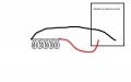
I have wind a coil with a copper ,air as a core and made a LC oscillator circuit with 640nF capacitor but when i see the oscillating frequency it was around 240K Hz.when i measure the inductance using LCR meter the value shown was 2.2uH .
But when i calculate the inductance using formula F=1/(2*pi*sqr(lc)) i got 700nF .
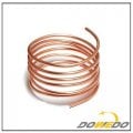
find the attached image to know my test setup .
Please let me know how to measure inductance value of a pure copper coil
I have wind a coil with a copper ,air as a core and made a LC oscillator circuit with 640nF capacitor but when i see the oscillating frequency it was around 240K Hz.when i measure the inductance using LCR meter the value shown was 2.2uH .
But when i calculate the inductance using formula F=1/(2*pi*sqr(lc)) i got 700nF .
find the attached image to know my test setup .
Please let me know how to measure inductance value of a pure copper coil
Attachments
-
 39.8 KB Views: 24
 -
 46.2 KB Views: 25


