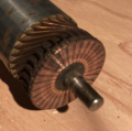
How to make a series-wound motor reversible?

MaxHeadRoom

Joined Jul 18, 2013
30,759
If the DC motor is a wound-field motor then it will rotate in the same direction regardless of the applied polarity. I own several electric drill motors like that. To reverse a brushed rotor motor the polarity of the field frlative to the armature must be reversed.
As per post 2 & 11!
 

MisterBill2

Joined Jan 23, 2018
27,896
As per post 2 & 11!
What becomes a bit confusing is that the sketch shows FOUR BRUSHES as I read it. At least, I am seeing four arrows that appear to indicate four brushes. THAT indicates to me that it is a four-pole motor. The good news is that the same scheme applies, but more caution is required to assure that the connections are all changed correctly.
So I suggest a more detailed examination of the connections area, as I have come across motors with connections identified as "A1 and A2" and "F1 and F2" . Those motors are already intended to be conveniently reversed. OR possibly they are not intended for series operation. There are also shunt-wound brush type motors.
 

LowQCab

Joined Nov 6, 2012
5,101
Sometimes Brushed-Motors have "lead" or "lag" built into the "timing" of the Brush-Holder-Assembly.

This may mean that the Motor may run better in one direction as opposed to the opposite direction,
or that it might be more prone to overheating, and/or, have a loss of Power in a "reverse" direction.
.
.
.
 

Tonyr1084

Joined Sep 24, 2015
9,744
That is simple with a permanent magnet motor, but requires separate connections to the firld for a brushed motor. That reality has been understood for at least 100 years!!!!!
Yes, I agree. It DOES require separate connections.
Screenshot 2024-03-27 at 7.48.51 AM.png Screenshot 2024-03-27 at 7.48.31 AM.png
Here's what I see: Two brushes are held in a carrier on the back shell. Two more brushes are suspended on the wiring from the field windings. Looks to me like four brushes, and yes, my illustration is intended to show four brushes all 90˚ from the next. Two opposing brushes at 180˚ are (assuming) the power feed. Current travels through the rotor then out the second set of brushes that are connected to the field windings. If you assemble the motor 180˚ out of phase the motor will run in the opposite direction.

The TS wants to be able to switch the motors direction using a switch (again, assuming). Changing the polarity of the field windings will assuredly reverse the motor direction. There can be no argument. That's the reality I understand, and has probably been understood for a hundred years.
 

MaxHeadRoom

Joined Jul 18, 2013
30,759
There are also shunt-wound brush type motors.
Shunt, wound field DC motors almost always possess a separate fed, fixed field, the larger ones also had field loss protection (shut-down) , due to potentially dangerous possibility of run away rpm & motor destruction if field loss occurred. :(
 

MisterBill2

Joined Jan 23, 2018
27,896
OK, this motor is a whole lot more complicated than most which are TWO POLE motors.What I see is that the brush pairs are not simply put in parallel, but rather each pair is connected to a separate field winding pair. So I am thinking that the circuit presented is incorrect. I am guessing that each brush pair is connected to a different field coil pair. So we need for the TS to do some inspection to see if the two brush pairs are tied together or not. My guess is that they are tied to separate field coil pairs, for a very good reason that is challenging to explain.
Another consideration is that it looks like this motor is quite high powered, and that a reversing switch will need to carry a whole lot of amps. That means that operating this motor in the reverse direction will require 8 high current connections and a high current four pole double throw switch.
Given that this is an anchor lifting switch, how is dropping the anchor handled? My guess is that the "windlass" is actually a "Cathead" device intended to assist an individual hauling up an anchor, rather than as a drum-winding hoisting device.. For a true winch to lower and raise the anchor a new permanent magnet motor driven mechnaism should be used.

NOTE: A CATHEAD provides assistance to an operator who has looped the line around it and is pulling on that line, which the tightens the line's grip on the rotating portion. These were first produced by the CATERPILLAR company many, many years ago, when ropes were actually pulled by hard working people.
 

MaxHeadRoom

Joined Jul 18, 2013
30,759
Looks like a typical four pole series field (compound?) -motor to me, many were fitted with inter-poles, which were reversed easily.
They are typically older technology (older than I am o_O )
 

MisterBill2

Joined Jan 23, 2018
27,896
Still the armature poles can not be connected in parallel because that will cause shorted turns to exist in the armature. So reversing will require separate field reversing switches. AND that looks like at least a 30 amp motor, so it will not be a cheap switch nor thin wires. Thus my comments in post #26.
 

Tonyr1084

Joined Sep 24, 2015
9,744
So I am thinking that the circuit presented is incorrect.
Which circuit? My drawing? If it's incorrect then please explain. I happen to have high confidence it's not incorrect. But being wrong is something I'm used to. So correct me if I'm wrong. Power comes in on (lets say) the left brush and passes through the armature winding that is associated with the commutator pad that is 90˚ (for the sake of argument) the top brush. From there it goes to the first set of field windings then in series to the other set of field windings, then back to the commutator brush at the bottom. From there the current path goes again through the armature windings and out at the right commutator pad into the brush and on out. By changing the field windings you reverse the magnetic pull of the field. Thus, instead of the armature being attracted to one field winding and repelled by the other it's switched and now repelled by the first coil and attracted by the second.

At least that's what I think. If I'm wrong - school me.
 

MaxHeadRoom

Joined Jul 18, 2013
30,759
Power comes in on (lets say) the left brush and passes through the armature winding that is associated with the commutator pad that is 90˚ (for the sake of argument) the top brush. From there it goes to the first set of field windings then in series to the other set of field windings, then back to the commutator brush at the bottom.
Just to confirm my earlier post I referred to my copy of the motor winding 'Bible' 'Electric Motor Repair' by Robert Rosenberg, 1946 !
It shows the same set-up for a 4pole DC series motor. To reverse, the same as a two pole, the fields are simply reversed WRT the armature brushes.
 
Last edited:

MisterBill2

Joined Jan 23, 2018
27,896
OK, I had thought that the sets of brushes were simply in parallel, which does not work. But with the two sets isolated by the fields that works. On my screen the drawing is not perfectly clear.
Adjacent brushes in parallel do not work, in series as described would work.
And still, the armature of that motor looks quite a bit like the windings of a starter motor for a small automotive engine. So that would be quite a high current rated switch.
Is there any information about the current that motor draws while running?? What rating is the present power circuit use? My point being that while the circuit change is not horribly complex, the wiring would be quite Heavy Duty, and the reversing switch will not be small.
 

MisterBill2

Joined Jan 23, 2018
27,896
Connecting that way would result in two sets of short circuited windings on the rotor, it would appear. hat does not seem quite right.AT least not from how I see it.
 

MisterBill2

Joined Jan 23, 2018
27,896
OK, MAX, you got me on this one. It has been a lot of years since I took a 4-pole DC motor apart I think it was about October 1970. In the college parking lot where my starter refused to spin. Not sure what the problem was, but it worked when I put it back together.
 

Tonyr1084

Joined Sep 24, 2015
9,744
I've found back then that when a starter wouldn't turn over you just needed to rap on it with a screwdriver handle a few times. That would usually knock dirt out from the brushes and it would usually work. Another "Bang-on-it" trick was when my carburetor float stuck open and began flooding the engine with fuel. Wrap on the bowl and that would usually dislodge the valve and close it. But that just meant you were going to be doing a carb rebuild soon. I never reworked a starter though.
 
Hello IPsolutions. I was wondering if you got an answer to your problem. I have I believe the exact same motor on my winless that I have been fighting with for about two years now.
I believe we have a series wound DC motor. As you’ve learned in order to reverse the direction, you either have to reverse the field windings or the armature wiring‘s but not both. I believe our system does it through that strange four brush system. Numerous trips to, two different motor shops has proved futile for me. I would love to know what you have discovered, and if your motor now reverses directions as it should.
One kept trying to convince me it would only go one direction, despite the fact that I explained it raises and lowers an anchor!
 

Thread Starter

ipsolutions

Joined Mar 24, 2024
8
Thank you all for the helpful responses. I ended up making two more terminals to reverse the windings relative to armature. It took some careful drilling, insulating and soldering, but the motor is now reversible. With even a single solenoid.
 
Top