Facebook
 Google
 GitHub
 Linkedin
Hello All,
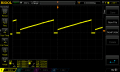
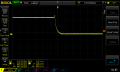
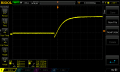
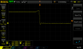
I am trying to make a Power BJT transistor switch have off-on and on-off transistion times less than one micro-second. At the moment I have a fall-time in the nano-second range(~8ns) and I have a rise-time in the range of ~2 micro-seconds.
I am trying to design the circuit such that this rise-time is below 1 micro-second. I am using a TIP41C Power BJT. When first connecting the circuit, the fall-time was ~20ns which I was able to decrease to ~8ns with the usage of "speed-up" capacitors.
I was trying the speed-up capacitors in order to decrease the amount of time it takes the base to discharge its charge thus decreasing the amount of time from on to off. Also, to provide a low impedance path to the base for the high frequency content of the pulsed trigger to trigger the base earlier which seems to work fine and decreased the off to on time. I am still not sure exactly how to size these capacitors because the transistors datasheet does not give a junction charge.
In the schematic the 5V source is a 1Hz, 10% duty cycle, 5Vpp square wave. I have attached the schematic, transistor's datasheet, and my two scope captures below. I have also attached the datasheets of two transistors which may work for my application(2SC5200, MJE15032) the reason I think they will work is because they have a transistion frequency of 30MHz as opposed to the TIP40C's transition frequency of 3MHz. I am also hoping they will have less input capacitance, but can't say for sure.
It is probably important to note that these measurements were taken on a 50MHz scope.
Any help is greatly appreciated.
Thanks
Attachments
-
177.3 KB Views: 5
-
72.7 KB Views: 3
-
 33.6 KB Views: 21
 -
 33.2 KB Views: 24
 -
 16.9 KB Views: 28
 -
414.5 KB Views: 4