How to make 9V battery to last longer in my PIC Micro controller Circuit

Picbuster

Joined Dec 2, 2013
1,062
My requirement is to power it from 9V so any battery composition will effect switching regulator operation or not?
Depending on model pic and number of led used.
use a linear regulator mcp1705 series 3,3V or 5V out 400mA qs 10 micro Amp approx.
put your cpu clock as low as possible e.q. 32Khz .
Adjust leds to 10mA max and use PWM to obtain max light at lowest PWM signal.
However all other in circuit resistors and will consume power.
@ pic's set unused port high no external resistor at unused ports.
A schematic of your design will allow us to evaluate currents.
Using fet's (voltage driven) in stead or transistors( current driven) could also save current. (could depending on circuit used)
Pic 18F8722 / mcp1705-3 / 32Khz @9V power takes in sleep mode 10 micro amp approx.
Awake 3mA approx (depending on configuration).
assume 10 leds @ 5mA = 50mA + 3mA cpu = 53mA permanent operational for 400/53 = 7Hrs approx.

Don't forget to send your schematic.

Picbuster
 

Ian Rogers

Joined Dec 12, 2012
1,136
12Mhz will work at 3.3v... I think the power requirement goes nuts after 16Mhz at 3.3v... I run mine at 1 Mhz... quick enough for low power solutions.

The slower you go, the less power is consumed.. Remember.. If it gets warm, well that's power being used..
 

MrSoftware

Joined Oct 29, 2013
2,280
My requirement is to power it from 9V so any battery composition will effect switching regulator operation or not?
As long as the battery can provide the required voltage and current, the battery chemistry should not affect the switching power supply (buck). Some buck controllers also have battery charging, and possibly battery protection (LiPo) built in.

Note that assembling your own buck converter can have challenges in regards to noise. There are fully complete buck converters on a module. For example, this one is probably much bigger than you need, but this is the idea:

https://www.mouser.com/ProductDetail/Murata-Electronics/LXDC2SCAAB-352?qs=/ha2pyFadugkNC5LJLVG2bGYEUgwcglcR3nBg3T%2bUNdaWL3AxIkqLYGR%2b8aCKKRg
 

Thread Starter

Faizan Zaheer

Joined Dec 20, 2017
8
Providing the microcontroller is specified to run at 3.3V and 16MHz then the frequency will be controlled by the crystal.
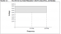
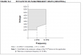
I have chosen the PIC16F88 Microcontroller and it is operation able on wide range of input voltage. In its datasheet, there are plots for frequency vs voltage, I think it is supply voltage vs oscillator frequency but I cannot be able to understand it. The link is given below:
http://ww1.microchip.com/downloads/en/devicedoc/30487d.pdf

Here is the image from datasheet on page 162:
Image1:
upload_2018-12-14_21-41-28.png
Image 2:
upload_2018-12-14_21-41-1.png
 

Thread Starter

Faizan Zaheer

Joined Dec 20, 2017
8
Depending on model pic and number of led used.
use a linear regulator mcp1705 series 3,3V or 5V out 400mA qs 10 micro Amp approx.
put your cpu clock as low as possible e.q. 32Khz .
Adjust leds to 10mA max and use PWM to obtain max light at lowest PWM signal.
However all other in circuit resistors and will consume power.
@ pic's set unused port high no external resistor at unused ports.
A schematic of your design will allow us to evaluate currents.
Using fet's (voltage driven) in stead or transistors( current driven) could also save current. (could depending on circuit used)
Pic 18F8722 / mcp1705-3 / 32Khz @9V power takes in sleep mode 10 micro amp approx.
Awake 3mA approx (depending on configuration).
assume 10 leds @ 5mA = 50mA + 3mA cpu = 53mA permanent operational for 400/53 = 7Hrs approx.

Don't forget to send your schematic.

Picbuster
Ok. I am using PIC16F88 Microcontroller in SSOP Package.
 

AlbertHall

Joined Jun 4, 2014
12,660
I have chosen the PIC16F88 Microcontroller and it is operation able on wide range of input voltage. In its datasheet, there are plots for frequency vs voltage, I think it is supply voltage vs oscillator frequency but I cannot be able to understand it. The link is given below:
http://ww1.microchip.com/downloads/en/devicedoc/30487d.pdf

Here is the image from datasheet on page 162:
Image1:
View attachment 165783
Image 2:
View attachment 165782
Yes, I interpret that as saying that it will operate at up to 20MHz with supply voltages above 4V.
The second diagram, for LF version, shows operation at lower voltages and lower maximum clock frequencies - 10MHz at 3V.

So 16MHz at 3.3V is outside the specification for the PIC16(L)F88.
 

Thread Starter

Faizan Zaheer

Joined Dec 20, 2017
8
Yes, I interpret that as saying that it will operate at up to 20MHz with supply voltages above 4V.
The second diagram, for LF version, shows operation at lower voltages and lower maximum clock frequencies - 10MHz at 3V.

So 16MHz at 3.3V is outside the specification for the PIC16(L)F88.
Thank you
 

Thread Starter

Faizan Zaheer

Joined Dec 20, 2017
8
If you want to know how much power each device in your system is actually taking, wire in some 1/4 or 1/2 ohm resistors and measure the voltage across them with a true RMS volt meter. Obviously remove these after debugging.

For the LED; By flashing he means PWM. You can often PWM an LED and it will look just as bright, or nearly as bright as an LED that is on continuously, however you will be saving power during the off time.

Also for your processor; you want to put the processor into low power mode as quickly and as often as possible. In a best case, connect your inputs to interrupts and put your processor to sleep until an interrupt wakes it. If the processor needs to actively check for inputs, then use a timer to wake it just long enough to check for inputs, then immediately go back to sleep. This way it actually spends most of its time sleeping and power drain becomes very small. Here's some code that fits with nordic processors, treat it as pseudo code and maybe you can apply the same general idea to your platform:

Code:
static volatile bool are_we_sleeping = false; /* This is set while we are sleeping, cleared by our wake up interrupt handler */
APP_TIMER_DEF(my_wakeup_timer); /* Declare our timer, your platform may use different syntax */

// This will be called when our wakeup timer expires
static void wake_up_interrupt_handler(void * p_context)
{
   are_we_sleeping = false;
}


// Create a timer that will wake us up from low energy state
void create_timer
{
    app_timer_create(&my_wakeup_timer, APP_TIMER_MODE_SINGLE_SHOT, wake_up_interrupt_handler);
}


/* Low power delay - set the wakeup timer for ms_delay milisec, then go to sleep for that amount of time */
uint8_t low_power_delay_ms(int ms_delay)
{
    // Start a timer that will wake up the processor via interrupt when the timer expires
    app_timer_start(my_wakeup_timer, APP_TIMER_TICKS(ms_delay, APP_TIMER_PRESCALER), NULL);
    /* Set the flag to indicate we're sleeping.  This will be cleared in the interrupt handler when we wake up */
    are_we_sleeping = true;

    /* Loop until our flag is cleared.  Note this loop will happen only once, see below */
    while(are_we_sleeping)
    {
        /* Put the processor to sleep.  Execution will stop here until we are woken up by the timer */
        power_manage();
    }
    return 0;
}

main()
{
    // Read our sensor 4x per second, entering low power state (sleeping) in-between
    while(1)
    {
        read_my_sensor();
        // Enter low power mode until we're ready to read again
        low_power_delay_ms(250);

    }
}
I want to drive four LEDs. It can be possible to drive four LED using PWM from PIC16F88. I think it is not possible?
 

Audioguru

Joined Dec 20, 2007
11,248
I am surprized that you are using an obsolete carbon-zinc battery. It had low power and leaked all over the place.
I usually use 9V alkaline batteries and a few times used a new 9V non-rechargeable Lithium battery that are much better than carbon-zinc.
New smoke detectors use the 9V Lithium battery that works for 10 years (if no smoke is detected for it to scream).

You want the LEDs to flash bright enough for 30ms, maybe a few times per second, not PWM at a high frequency because your eyes see the average of PWM which would dim the light.
 

Attachments

MrSoftware

Joined Oct 29, 2013
2,280
You can always add a mosfet to control the LEDs and use the pic to drive the gate of the mosfet. An n-channel will be most efficient.

As @Audioguru mentioned above, if it's OK for your LEDs to appear blinking instead of on solid, then another good option is to drive them directly (no PWM), but for a very short time. You can vary the delay between blinks for different indications, such as slow blink (1x/second) for one status, fast blink (4x/sec) for another status, just keep the "on" time short such as 30ms. The user will see that as a very bright but short blink.
 

takao21203

Joined Apr 28, 2012
3,702
The total is 150mA and that doesnt come from the LEDs

The sensor.
The controller frequency should be as low as possible, perhaps not max. frequency is required.

Normal LEDs can do with 2 or 3mA and flashing can reduce this much further.

I guess the sensor is the main issue.

You could use 2x AAA batteries perhaps almost same size as 9V and use a booster these USB boosters are very low cost and output 5V.

If you can reduce the controller voltage it will save more power maybe can run directly from 2x AAA battery
 
Top