Hello Ally860
.
You have many things to improve your design:
.
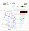
In short, because time is gone, remove the switch S1 and connects all 1's PIN directly to Vcc (+).
Left the current limiting resistors for all segments of all Display's.
To add functions that are requiring examines the PDF document I am enclosing you.
.
I hope I've helped.
Hello Ally860
.
You have many things to improve your design:
.
In short, because time is gone, remove the switch S1 and connects all 1's PIN directly to Vcc (+).
Left the current limiting resistors for all segments of all Display's.
To add functions that are requiring examines the PDF document I am enclosing you.
.
I hope I've helped.
In the Homework Help forum providing the direct answer is not what this forum should be, so I deleted the attached file, guiding is the best way to do, please don't do that again, thank you.
The lack of time is often created by starting to late with the project.
They will have to learn how to plan their free-time and the time needed for school.
Students, and I'm not saying the OP is one of them, sometimes try to use our best intentions to "trick" us into doing their thinking for them. It takes restraint to not simply give them the answer when it appears that they're floundering; but it's important for them to learn what it takes to be successful. If they don't have it, then they can choose another vocation while they still have time. I don't visit this forum very frequently because of the often times glacial pace that progress is made; this one started in General and was moved, otherwise, I probably wouldn't have seen it.
I did look at your circuit before it was removed. It was an example of a well thought out schematic; though I didn't care for the, heavy for my taste, use of off sheet connectors.
What simulator are you using? How does the 3rd stage get clocked? I looked at the timing diagrams for the counter and did a cursory analysis of the carry out logic and the counter won't generate a carry out pulse to clock the 3rd stage when it's reset. I assume your simulator showed you a functioning circuit.
The OP was using Multisim and, apparently, it was showing him correct operation when he had a couple logic issues. That's one of my biggest complaints about novices using simulators before they have a good grasp of fundamentals.
Students, and I'm not saying the OP is one of them, sometimes try to use our best intentions to "trick" us into doing their thinking for them. It takes restraint to not simply give them the answer when it appears that they're floundering; but it's important for them to learn what it takes to be successful. If they don't have it, then they can choose another vocation while they still have time. I don't visit this forum very frequently because of the often times glacial pace that progress is made; this one started in General and was moved, otherwise, I probably wouldn't have seen it.
I did look at your circuit before it was removed. It was an example of a well thought out schematic; though I didn't care for the, heavy for my taste, use of off sheet connectors.
What simulator are you using? How does the 3rd stage get clocked? I looked at the timing diagrams for the counter and did a cursory analysis of the carry out logic and the counter won't generate a carry out pulse to clock the 3rd stage when it's reset. I assume your simulator showed you a functioning circuit.
The OP was using Multisim and, apparently, it was showing him correct operation when he had a couple logic issues. That's one of my biggest complaints about novices using simulators before they have a good grasp of fundamentals.
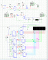
Well i am expecting guide because i want to it by my own effort and score the marks in the right way. And yes, we got the assignment in mid November, where exams started week next and lasted 3 weeks. I immediately started after exams from the 9th of December, and browsing thru all possible websites and designs i've made it to this extent so far. But now i am stuck with the pause and reset. For Reset, only the frame displays 00:00, but timer continues running in the background. Can u advice me from the snippet am attaching with? Pleaase
Well i am expecting guide because i want to it by my own effort and score the marks in the right way. And yes, we got the assignment in mid November, where exams started week next and lasted 3 weeks. I immediately started after exams from the 9th of December, and browsing thru all possible websites and designs i've made it to this extent so far. But now i am stuck with the pause and reset. For Reset, only the frame displays 00:00, but timer continues running in the background. Can u advice me from the snippet am attaching with? Pleaase
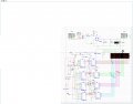
Using the gif file format for the circuit is better, the png only for single color and vertical line and horizontal line, I was converted the file format from png to gif and cut off the rest space part, the file size from about 5Mb to 83kb.
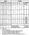
Have you read the datasheet for the display driver?
This excerpt shows that the digit displayed depends on what was displayed before LD was taken LOW. The only time your reset would show zeros on the display is when it was already displaying zero. What you want to do is reset the counters. Look at counter functionality to see if it provides a way.
Yes i am sorry. Mistake on my part; it is indeed reset of 4510! what i meant that by resetting the display, the counter should also b reset in another way. bCoz the display displays the process happening. I have tried on my own and i am being able to reset the seconds and only the first minute display, that is the Xs in YX:XX . The seconds are incrementing the minute at 60s but they continue to 99s, then start again 00s to 60s again to re increment minute again and goes till 99s again and so on and so forth...
Thanks for the advice concerning snippet format, ill use it later.
And concerning the arrow in the snippet. When i am resetting, as the timer starts again, it starts with 1, that is, reset => 00:10 instead of 00:00
Yes i am sorry. Mistake on my part; it is indeed reset of 4510! what i meant that by resetting the display, the counter should also b reset in another way. bCoz the display displays the process happening. I have tried on my own and i am being able to reset the seconds and only the first minute display, that is the Xs in YX:XX . The seconds are incrementing the minute at 60s but they continue to 99s, then start again 00s to 60s again to re increment minute again and goes till 99s again and so on and so forth...
Thanks for the advice concerning snippet format, ill use it later.
And concerning the arrow in the snippet. When i am resetting, as the timer starts again, it starts with 1, that is, reset => 00:10 instead of 00:00
What logic level does reset require? Why are you using 3 separate switches? What you want is to reset all 4 counters with one control. Look at the reset logic and see if you can determine why the most significant digit isn't resetting.
From the way you have reset wired, nothing should be resetting.
How come it won't work, it works just fine?
Do you have any problem to show the gif file format?
Have you seen the circuit that I modified and showed it in #34?
well the 3 separate switches are for the 3 resets in the 4510 IC, by trial and error, i could do a reset. the fourth 4510 ic am not being able to connect it properly. And why does it start with 00:10? i had a similar problem before but i dont remember what change caused it stopped, i guess it was high voltage or lower frequency.

 Facebook
 Google
 GitHub
 Linkedin