How to implement LM35 and 555 Timer together

Thread Starter

RCed

Joined Feb 14, 2015
2
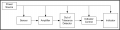
Design, implement, and test a Signal Conditioning Circuit that will provide an output voltage in the range of V1 to V2 when room temperature changes from T1 ºC to T2 ºC.
Also, if the room temperature is more than T3 ºC but less than T4 ºC, a red LED shall FLASH at a frequency of F1 Hz with a duty-cycle of D1 %.
For Window Comparator, you shall utilize open-collector output comparators.


At least one reference voltage will be obtained by using a zener diode (this is needed to satisfy the constraint of obtaining constant reference voltage even if the supply voltage changes).
For any other reference voltage you may use potentiometer.

How should i Design the circuit of this project ?

Thanks
 

WBahn

Joined Mar 31, 2012
29,979
You should design it to satisfy the given specifications.

You might try breaking the problem down into pieces. Which tasks depend on other tasks? Can tasks be broken into modules that can then be interconnected.

Where are the parameters -- V1, V2, T1, ... -- coming from? Are they constants that you know ahead of time?
 

Thread Starter

RCed

Joined Feb 14, 2015
2
You should design it to satisfy the given specifications.

You might try breaking the problem down into pieces. Which tasks depend on other tasks? Can tasks be broken into modules that can then be interconnected.

Where are the parameters -- V1, V2, T1, ... -- coming from? Are they constants that you know ahead of time?
The V1, V2,.... Will be given to me later, i should assume it for now.
i have made a design, but im not sure if its the right way

Moderators note: rotated cropped and resized image
 

Attachments

Last edited by a moderator:

bertus

Joined Apr 5, 2008
22,270
Hello,

When using open collector comparators, a pull-up resistor must be used.

The LM35 only gives 10 mV / C.
Perhaps amplifying the LM35 signal might give you more reasonable voltages for the comparators.

Bertus
 

JoeJester

Joined Apr 26, 2005
4,390
WBahn,

I know block diagrams are "old school" technology, but I see where they can play an important part in the learning process. I just don't see any of the questions here in the homework section, or the homework section at ETO, where anyone breaks their requirements to blocks to assist in their design.

It just seems that block diagrams are a thing of the past ... when they could be of great assistance today. Granted, in a lot of the cases, the functional block ends up being a single chip. The focus on chip selection and circuit design could be a lot easier if the student has a better feel of what their design is to accomplish internally.

That's my observation over the past decade of reading homework threads.
 

shteii01

Joined Feb 19, 2010
4,644
Yep. Forget the parts. Start with block diagram. Once you got the blocks, and blocks inside the blocks, then you can pencil in the actual parts.
 

crutschow

Joined Mar 14, 2008
34,285
Block diagrams may be "Old School" but I think they are still very relevant and still used in the industry as the first step in designing a circuit of any significant complexity.
I agree it should be emphasized here in the Homework section as the first step to clarify what needs to be done to perform the required functions.
One of the first questions by the OP is often "Where do I start" and the answer to that should be "Block Diagram".
 

JoeJester

Joined Apr 26, 2005
4,390
WBahn

I was seeking your opine, not questioning your post.

Of course if tthe TS is just seeking the amswer, then the block diagram is a moot point.
 

WBahn

Joined Mar 31, 2012
29,979
Ah. Well I definitely agree with you.

Breaking a problem down into smaller chunks (what is called "problem decomposition" in the edu-speak lingo) is still the normal approach that is recommended, but it is generally getting lost in the mix. I have some thoughts on why, but don't know that any of them really sum things up well. Personally I think that we have just gotten so far away from fundamentals and have become so enamored with abstract, pre-packaged solutions even in situations when the fundamentals should be what it's all about, that we are crippling people we are supposed to be educating.
 

JoeJester

Joined Apr 26, 2005
4,390
I always thought the purpose of this section was to help and if block diagrams help, that should be the first question asked of the TS who "doesn't have a clue" on where to start.

Even the problem in this discussion, the basic blocks included the sensor, the comparator, the flasher, and the indicators. Each were bite sized blocks, with some being a single chip. It was recommended by bertus to add an amplifier ... a "new" block between the sensor and comparator with it's own design specifications to be determined by the TS.

I don't know if the demands of the members has frightened off the TS or not. We shall see.

To the TS's question of
How should i Design the circuit of this project ?
I'd say, fill in what you know about each of these blocks. power, input, and output ... it's up to you to flesh out your design. This block diagram is the skeleton.
 

Attachments

Top