How to get + 15VDC and -15VDC from AC Source

Thread Starter

mlwinters

Joined Dec 22, 2015
7
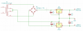
Hi there, I am designing a power supply for a project. I have a 24V dual secondary transformer and I need to get +15VDC and -15VDC from 7815 and 7915 voltage regulators via bridge rectifiers.

I have made a crude drawing of what I think I need to do in order to achieve this. Would you mind checking it and let me know if I have done this correctly.

Thanks a lot for your time and help.
Morgan
 

Attachments

Dodgydave

Joined Jun 22, 2012
11,285
Yes or you can use one bridge rectifier and tie pins 4/5 of the Transformer together as your Gnd signal, and put pins 3/6 to the bridge rectifier.
 

ericgibbs

Joined Jan 29, 2010
18,767
Hi Morgan.
Need to add 100nF caps at the Inp and Out of the regulators, also a 470uF cap or so on the Outputs.
What sort of current output are you requiring.?
E
 

Thread Starter

mlwinters

Joined Dec 22, 2015
7
Firstly thank you both so much for your lightning fast replies.

Yes or you can use one bridge rectifier and tie pins 4/5 of the Transformer together as your Gnd signal, and put pins 3/6 to the bridge rectifier.
If I understand you correctly, is the attached image on this post what you mean? If so, this would be a much better solution as is cuts down on wiring thus making the PCB smaller (space is a limiting factor with this project) and uses less components which I'm all in favor of doing.


Hi Morgan.
Need to add 100nF caps at the Inp and Out of the regulators, also a 470uF cap or so on the Outputs.
What sort of current output are you requiring.?
E
Yes indeed, I just didn't add C3 and C4 to the first image but I did to the image attached to this post. These are components I know I need to add but just wanted to check with you the wiring of the circuit before C3 and C4.
I haven't breadboarded the system yet so I don't know exactly the current draw yet but it should be upto around the 750-800mA range.

Thank again for your fast replies and help
Morgan
 

Attachments

ericgibbs

Joined Jan 29, 2010
18,767
hi M,
Be aware that 24Vrms will give a ~ 1.414 *24v ~ 36Vdc - two diode drops of 0.7v , so say 34V
Dropping from 34V down to 15V is a 19Vpk drop.
Without heatsinks on the regs, allow a max dissipation of 2Watts, so thats 2W/19V = 100mA worst case.

If you consider 24Vdc -1.4V = 22.6V.... so down to 15V is a 7.6V drop... so at 2Watts/7.6V = ~270mA.

So you will require heatsinks for the regs.

E
 

bertus

Joined Apr 5, 2008
22,270
Hello,

The input voltage also is close to the maximum allowed for an 78 or 7915 of 35 Volts.
Better try to find a transformer with a lower voltage.
A lower input voltage will reduce the power wasted in the regulators.

Bertus
 

Attachments

Thread Starter

mlwinters

Joined Dec 22, 2015
7
hi M,
Be aware that 24Vrms will give a ~ 1.414 *24v ~ 36Vdc - two diode drops of 0.7v , so say 34V
Dropping from 34V down to 15V is a 19Vpk drop.
Without heatsinks on the regs, allow a max dissipation of 2Watts, so thats 2W/19V = 100mA worst case.

If you consider 24Vdc -1.4V = 22.6V.... so down to 15V is a 7.6V drop... so at 2Watts/7.6V = ~270mA.

So you will require heatsinks for the regs.

E
Thanks for the heads up. That 750-800mA number I gave is my estimate of current draw from the transformer not from each regulator. The 7815 current draw should be around 450-500mA and the 7915 current should be about 250mA. Sorry I should have made this clear in my last post.
I already have these heatsinks I had from another project. I also plan on adding a 60mm fan at the back of the 19" rack unit blowing directly onto the voltage regulators to ensure that temperatures are kept within a reasonable range.


Hello,

The input voltage also is close to the maximum allowed for an 78 or 7915 of 35 Volts.
Better try to find a transformer with a lower voltage.

Bertus
Forgive me but may I ask why a transformer rated 11V lower than the max input voltage of the regulators matters? Even accounting for the error that transformer normally have, the voltage is still around 6V lower than the max input voltage. Does using ST regulators instead of FCI make any difference to this?

Thanks again for your replies.
Morgan
 

bertus

Joined Apr 5, 2008
22,270
Hello,

The peak voltage is √2 times higher than the RMS value of the transformer.
There is one diode voltage drop.
So the capacitor voltage is (√2 * 24) - 0.7 Volts = 33.9 - 0.7 = 33.2 Volts.

The shown heatsink are very small for the amount of power to be dissipated.
The 7815 will have to dissipate ( 33.2 - 15 ) * 0.5 = 9.1 Watts.
The capacity of the shown heatsink is 19°/W, so it will become 9.1 * 19 = 172°C above the enviroment temperature.
Better use a heatsink like this : https://www.rapidonline.com/aavid-t...-to218-and-to220-4-4-c-w-bolt-on-type-36-0275
Then the temperature will become 9.1 * 4.4 = 40°C above the enviroment temperature.

Bertus
 

ericgibbs

Joined Jan 29, 2010
18,767
hi,
What is the spec on the transformer.?
24Vdc -1.4V = 22.6V.... so down to 15V is a 7.6V drop... so at 7.5V * 0.8Amp = 6Watts. so those H/S you have are rated at 19C/W, they will run very hot.
The fan will help of course, if directed at the regs.

E
 

MrChips

Joined Oct 2, 2009
30,720
Do you have a choice on the transformer?
A 15V-0-15V secondary will provide enough headroom and lower the heat generated by the regulators.
 

Thread Starter

mlwinters

Joined Dec 22, 2015
7
First off, sorry for the delay in posting this reply, I have had serveral family emergencies over the last couple of weeks so please forgive me if I don't reply straight away.

The capacity of the shown heatsink is 19°/W, so it will become 9.1 * 19 = 172°C above the enviroment temperature.
Bertus
:eek: Wow 172°C above ambient, that's totally unacceptable.......back to the drawing board as they say lol.


I have looked over the numbers and it does indeed seem I completely misjudged the size of the heatsinks needed for this project (big thank you for bringing this error to my attention :)). I have therefore temporarily added 2 of those 4.4°C/W heatsinks @bertus suggested onto my cart on Rapid to be ordered. However, I just wanted to check, given that Rapid sell a slightly bigger version of that same heatsink rated at 3.3°C/W, would be not be better to order that instead? From my understanding, if I use a bigger heatsink, the voltage regulators would run a little cooler and give me more breathing space to add other things to the system, e.g an OLED display without needing to worry above thermals. These bigger heatsinks are the same size as that 4.4°C/W versions but 12.7mm taller. When taking into account of the thickness of the PCB, PCB standoffs and the heatsink, this gives 12.6mm space between the top of the heatsink and the top of the rack unit I plan on putting this system in. In your experience, would this be sufficient? As already stated, I plan on putting a small fan blowing air directly onto the voltage regulators just to be on the safe side.

@ericgibbs This is the transformer I will be using.


@MrChips Sadly no, I already had this transformer for another project that I decided not to build and would prefer not to have to buy a different unit if at all possible.

Can I just double check, that second schematic I posted, does that look ok to you guys? I just wanted to check before I start designing the PCB.

Once again, thank you all so much for your expert help and advice with this. I really appreciate it :D.
Morgan
 

TeeKay6

Joined Apr 20, 2019
573
First off, sorry for the delay in posting this reply, I have had serveral family emergencies over the last couple of weeks so please forgive me if I don't reply straight away.


:eek: Wow 172°C above ambient, that's totally unacceptable.......back to the drawing board as they say lol.


I have looked over the numbers and it does indeed seem I completely misjudged the size of the heatsinks needed for this project (big thank you for bringing this error to my attention :)). I have therefore temporarily added 2 of those 4.4°C/W heatsinks @bertus suggested onto my cart on Rapid to be ordered. However, I just wanted to check, given that Rapid sell a slightly bigger version of that same heatsink rated at 3.3°C/W, would be not be better to order that instead? From my understanding, if I use a bigger heatsink, the voltage regulators would run a little cooler and give me more breathing space to add other things to the system, e.g an OLED display without needing to worry above thermals. These bigger heatsinks are the same size as that 4.4°C/W versions but 12.7mm taller. When taking into account of the thickness of the PCB, PCB standoffs and the heatsink, this gives 12.6mm space between the top of the heatsink and the top of the rack unit I plan on putting this system in. In your experience, would this be sufficient? As already stated, I plan on putting a small fan blowing air directly onto the voltage regulators just to be on the safe side.

@ericgibbs This is the transformer I will be using.


@MrChips Sadly no, I already had this transformer for another project that I decided not to build and would prefer not to have to buy a different unit if at all possible.

Can I just double check, that second schematic I posted, does that look ok to you guys? I just wanted to check before I start designing the PCB.

Once again, thank you all so much for your expert help and advice with this. I really appreciate it :D.
Morgan
@mlwinters

Please be aware that transformers are specified by their performance at full rated load; at a lesser load the output voltage of the transformer will be higher--how much higher depends on the specific transformer. Before you proceed further, I suggest you measure the output of your transformer at no load and with the primary driven by the highest AC line voltage--not the nominal voltage, e.g. 115VAC--but the highest voltage that you want your circuit to survive. For a normal 115VAC line, long duration excursions to 120VAC are common. Thus, if the transformer you have is rated for a 115VAC primary, then a 120VAC primary will raise the secondary by the same ratio: 120/115*24=25VAC at full load. The only way to find how high the secondary voltage can go under light load is to measure it under light load.

As has been noted by other commenters, you will likely be operating the LM7815/LM7915 at or above their Absolute Max input voltage ratings. From experience, I can tell you that those IC's will not be happy. Worse, insufficient heat sinking will cause the devices to automatically shut down (if you are lucky; otherwise, they will just melt or explode). We (AAC commenters) don't make the devices or the laws of physics, but we have to live within them.

There are solutions to this situation, but they are rather complicated compared to what you have proposed. Namely, the linear regulators could be replaced by SMPS (switch mode power supplies) to efficiently lower the voltage to 15V so that huge heatsinks would not be needed and the SMPS (that you design or, preferably, buy) can tolerate the high transformer voltage. Also, the SMPS solution is not free of cost.
 

ericgibbs

Joined Jan 29, 2010
18,767
hi Morgan,
That transformer is rated at only 20VA, so assume 10VA per secondary at 24Vrms, that's approx 10VA/24Vac = 0.4A per winding.
If you require 0.8A for say both regulators that's 1.6A *24V =~40VA, I would suggest not less than 60VA transformer rating
E
 

Dodgydave

Joined Jun 22, 2012
11,285
First off, sorry for the delay in posting this reply, I have had serveral family emergencies over the last couple of weeks so please forgive me if I don't reply straight away.


:eek: Wow 172°C above ambient, that's totally unacceptable.......back to the drawing board as they say lol.


I have looked over the numbers and it does indeed seem I completely misjudged the size of the heatsinks needed for this project (big thank you for bringing this error to my attention :)). I have therefore temporarily added 2 of those 4.4°C/W heatsinks @bertus suggested onto my cart on Rapid to be ordered. However, I just wanted to check, given that Rapid sell a slightly bigger version of that same heatsink rated at 3.3°C/W, would be not be better to order that instead? From my understanding, if I use a bigger heatsink, the voltage regulators would run a little cooler and give me more breathing space to add other things to the system, e.g an OLED display without needing to worry above thermals. These bigger heatsinks are the same size as that 4.4°C/W versions but 12.7mm taller. When taking into account of the thickness of the PCB, PCB standoffs and the heatsink, this gives 12.6mm space between the top of the heatsink and the top of the rack unit I plan on putting this system in. In your experience, would this be sufficient? As already stated, I plan on putting a small fan blowing air directly onto the voltage regulators just to be on the safe side.

@ericgibbs This is the transformer I will be using.


@MrChips Sadly no, I already had this transformer for another project that I decided not to build and would prefer not to have to buy a different unit if at all possible.

Can I just double check, that second schematic I posted, does that look ok to you guys? I just wanted to check before I start designing the PCB.

Once again, thank you all so much for your expert help and advice with this. I really appreciate it :D.
Morgan
Your best solution to avoid heat waste is to use buck regulators like LM2596, theses are ok upto 3Amps,,otherwise use a lower output transformer..


im130731002_8.jpg
 

Thread Starter

mlwinters

Joined Dec 22, 2015
7
Thank you for your replies and again sorry for the delay in posting this.

@mlwinters

Please be aware that transformers are specified by their performance at full rated load; at a lesser load the output voltage of the transformer will be higher--how much higher depends on the specific transformer. Before you proceed further, I suggest you measure the output of your transformer at no load and with the primary driven by the highest AC line voltage--not the nominal voltage, e.g. 115VAC--but the highest voltage that you want your circuit to survive. For a normal 115VAC line, long duration excursions to 120VAC are common. Thus, if the transformer you have is rated for a 115VAC primary, then a 120VAC primary will raise the secondary by the same ratio: 120/115*24=25VAC at full load. The only way to find how high the secondary voltage can go under light load is to measure it under light load.

As has been noted by other commenters, you will likely be operating the LM7815/LM7915 at or above their Absolute Max input voltage ratings. From experience, I can tell you that those IC's will not be happy. Worse, insufficient heat sinking will cause the devices to automatically shut down (if you are lucky; otherwise, they will just melt or explode). We (AAC commenters) don't make the devices or the laws of physics, but we have to live within them.

There are solutions to this situation, but they are rather complicated compared to what you have proposed. Namely, the linear regulators could be replaced by SMPS (switch mode power supplies) to efficiently lower the voltage to 15V so that huge heatsinks would not be needed and the SMPS (that you design or, preferably, buy) can tolerate the high transformer voltage. Also, the SMPS solution is not free of cost.
Firstly I should point out that the I choose to use a dual primary transformer due to the 19" rack unit I have has a voltage selection switch on the back that was installed by the manufacturer of the device before I ripped everything out of it. I wanted to keep this voltage selection switch in place and for it to be functional so I didn't have to cut and weld in a blanking plate in it's place, which to me looks ugly. The new power supply I want to build will run on practically always run at 230VAC and I don't imagine I will ever run it on 115VAC but I want to have that option of being able to should I need to without needed an external transformer. While the unit is running on 230VAC I will place a clear plastic cover over the voltage selection swtich to prevent accidental changes.

After seeing your's and ericgibbs reply I have now scrapped the idea of using the 24V/20VA transformer, see below.

As for switch mode power supplies. I have never built or play around with switch mode supplies before and for this project, since I am building almost all of it from scratch, I would want to built the power supply as well. However, due to lack of experience with SMPS's I feel that building a switch mode would be beyond me at this point. I may upgrade this unit to have a SMPS once I have made a test version later on but for now I will stick with a linear power supply. I could buy a premade one but that would defeat the point of this project. That said I very much value your advice and I will look into building one to play around with after this project. I have another project lined up after this one that a SMPS will be the best solution so you have my word that I will find out how they work and build one to play with.
I am thinking of getting a transformer with an output voltage of 20V, this should allow the 7815 and 7915 to be within to 35V that ST state in the datasheet when you take into account of the 22-26V that the transformer would acutally output during low current draw. Can you confirm this?


hi Morgan,
That transformer is rated at only 20VA, so assume 10VA per secondary at 24Vrms, that's approx 10VA/24Vac = 0.4A per winding.
If you require 0.8A for say both regulators that's 1.6A *24V =~40VA, I would suggest not less than 60VA transformer rating
E
Now that you mention that, your are right, this transformer is not enough for this project. Although the 800mA number is the peak current I would pull from it, the current per winding is not good enough for this project.
I have measured the currrent of different parts of this project, the max current from the +15V would be around the 550mA mark but this is still above the 400mA rating of the transformer winding. The -15V side will only there for 3 opamps so we're not talking a huge amount for the 7915 but still. I have looked around on Rapid's website and the next suitable transformer would be a 20V/50VA unit. This would give 1.25amp per winding which should be enough for this project. Rapid don't sell a a 60VA unit (only a 63VA which is a bit pricey) or a 75VA which again is a bit too pricey and since I only have a limit space to work inside of, the 75VA is a bit too big to allow me to install the other parts of the system I need to add.
So for the current Ill be drawing would the 20V/50VA transformer be the best option?

By lowing the voltage from 24V down to 20V (Rapid don't sell 18V which would have been better) the voltage regulators should than generate less heat that I need to control. If I where to still get those 4.4°C/W heatsinks together with a fan would this be enough. Could you check I have run the numbers correctly please. 20V transformer, 5V drop over regulators to 15V and with an absolute max current of 0.8A. Therefore 5V * 0.8A = 4Watt. 4Watt * 4.4°C/W = 17.6°C above ambient.
If I have that correct, 17.6°C above ambient without taking into account the cooling fan to me sounds reasonable. Much better than the 172°C I was looking at before your advice.


Your best solution to avoid heat waste is to use buck regulators like LM2596, theses are ok upto 3Amps,,otherwise use a lower output transformer.
As I said above, I have never used or played around with SMPS or indeed a buck regulator so building one would be beyond me at this point until I experiment around with one. This is something I plan to do later but not at this stage. I also don't wish to buy a pre-made unit as I want to build this system myself. Making this system to have maximum efficiency isn't a concern at this stage so I am happy with having large heatsinks provided that the temperatures are within reasonable level. Thanks for the advice though ;).

Thanks again for your ongoing help and furthering my understanding with electronics. I really appreciate you helping me like this.
 

TeeKay6

Joined Apr 20, 2019
573
Thank you for your replies and again sorry for the delay in posting this.


Firstly I should point out that the I choose to use a dual primary transformer due to the 19" rack unit I have has a voltage selection switch on the back that was installed by the manufacturer of the device before I ripped everything out of it. I wanted to keep this voltage selection switch in place and for it to be functional so I didn't have to cut and weld in a blanking plate in it's place, which to me looks ugly. The new power supply I want to build will run on practically always run at 230VAC and I don't imagine I will ever run it on 115VAC but I want to have that option of being able to should I need to without needed an external transformer. While the unit is running on 230VAC I will place a clear plastic cover over the voltage selection swtich to prevent accidental changes.

After seeing your's and ericgibbs reply I have now scrapped the idea of using the 24V/20VA transformer, see below.

As for switch mode power supplies. I have never built or play around with switch mode supplies before and for this project, since I am building almost all of it from scratch, I would want to built the power supply as well. However, due to lack of experience with SMPS's I feel that building a switch mode would be beyond me at this point. I may upgrade this unit to have a SMPS once I have made a test version later on but for now I will stick with a linear power supply. I could buy a premade one but that would defeat the point of this project. That said I very much value your advice and I will look into building one to play around with after this project. I have another project lined up after this one that a SMPS will be the best solution so you have my word that I will find out how they work and build one to play with.
I am thinking of getting a transformer with an output voltage of 20V, this should allow the 7815 and 7915 to be within to 35V that ST state in the datasheet when you take into account of the 22-26V that the transformer would acutally output during low current draw. Can you confirm this?


Now that you mention that, your are right, this transformer is not enough for this project. Although the 800mA number is the peak current I would pull from it, the current per winding is not good enough for this project.
I have measured the currrent of different parts of this project, the max current from the +15V would be around the 550mA mark but this is still above the 400mA rating of the transformer winding. The -15V side will only there for 3 opamps so we're not talking a huge amount for the 7915 but still. I have looked around on Rapid's website and the next suitable transformer would be a 20V/50VA unit. This would give 1.25amp per winding which should be enough for this project. Rapid don't sell a a 60VA unit (only a 63VA which is a bit pricey) or a 75VA which again is a bit too pricey and since I only have a limit space to work inside of, the 75VA is a bit too big to allow me to install the other parts of the system I need to add.
So for the current Ill be drawing would the 20V/50VA transformer be the best option?

By lowing the voltage from 24V down to 20V (Rapid don't sell 18V which would have been better) the voltage regulators should than generate less heat that I need to control. If I where to still get those 4.4°C/W heatsinks together with a fan would this be enough. Could you check I have run the numbers correctly please. 20V transformer, 5V drop over regulators to 15V and with an absolute max current of 0.8A. Therefore 5V * 0.8A = 4Watt. 4Watt * 4.4°C/W = 17.6°C above ambient.
If I have that correct, 17.6°C above ambient without taking into account the cooling fan to me sounds reasonable. Much better than the 172°C I was looking at before your advice.


As I said above, I have never used or played around with SMPS or indeed a buck regulator so building one would be beyond me at this point until I experiment around with one. This is something I plan to do later but not at this stage. I also don't wish to buy a pre-made unit as I want to build this system myself. Making this system to have maximum efficiency isn't a concern at this stage so I am happy with having large heatsinks provided that the temperatures are within reasonable level. Thanks for the advice though ;).

Thanks again for your ongoing help and furthering my understanding with electronics. I really appreciate you helping me like this.
@mlwinters
I can only confirm that your newly proposed transformer seems likely to work acceptably. For the LM7815/LM7915, proper operation requires that the DC input to the regulators is at least several(3) volts above the output voltage. Note that this minimum input voltage will occur when: (a) AC line is at minimum, (b) output load is maximum, (c) ripple in rectified output of transformer (i.e. input to regulator) is at an instantaneous minimum (i.e. the "valley" of the ripple waveform). Heat sinking of regulators remains highly important. My experience with the LM78xx regulators is that operation near max input voltage (e.g. 32-35V) is marginal and that the built-in protection (over temp) does not always save the device. I strongly encourage the use of a fuse(s) in either the primary or secondary of the transformer. If you intend your power supply for general use (i.e. not just internal to one project), I suggest that over-voltage and over-current protection of the output be considered (e.g. a crowbar circuit or current limiting). If a power supply fails, it could destroy expensive circuitry that uses its output(s). Likewise, if a load fails and draws too much current, the power supply may fail...and in turn cause even more damage to power supply and load.
 
Top