An audio amplifier can increase the level. Example the FG-100b DDS are inexpensive. The work horse is the amp. The FG is mostly just a signal source.
With the addition of an adjustable amplifier the output might give for example an adjustable output from 0-28 Vpp and 0 -50 mA. Video shows the FG
I use an R2R on the Arduino PortB in a VHF transceiver to generate sub tones. Here is part off the code...
This version has not been tested but it compiles ok.
And a buffer amp will be needed on the output, as will an R/C filter.
Code:
#define RefFrequ      500000        // 16Mhz / 32 steps for CTCSS sine wave generator

int    SineDivider = 4065;         // default sine wave divider
int    ToneFrequ = 60;
int  i ;

int sinetable[] // one cycle sine wave via R2R network.

{ 0,1,2,3,5,7,10,13,16,19,22,25,27,28,29,30,31,30,29,28,27,25,22,19,16,13,10,7,5,3,2,1, };

void setup ()
{
    DDRB  = B111111;                // sets Arduino pins 7 to 12 as outputs.
    PORTB = B100000;                // R2R out at rest to half level.
    SineDivider = (RefFrequ/(ToneFrequ));
}

void loop ()
{
      Generate_Tone();   // start the tone
      delay(1000);
      TIMSK1 = 0;        // tone off
      delay(1000);
}

void Generate_Tone()
{
  cli();                    // interupsts off for setup
  TCCR1A = 0;               //
  TCCR1B = 0; //B00000010;       //  no prescaler
   // set compare match register for 1hz increments
  OCR1A = SineDivider ;// = (16*10^6) / (1*1024) - 1 (must be <65536)
  // turn on CTC mode
  TCCR1B |= (1 << WGM12);
  // Set CS10 no prescaler
  TCCR1B |= (0 << CS12) | (0 << CS11) | (1 << CS10);
  // enable timer compare interrupt
  TIMSK1 |= (1 << OCIE1A);
  sei();                    // interupsts on
}

ISR(TIMER1_COMPA_vect){
  PORTB=(sinetable[i++]);   // write value from table to PORTB
  if(i>=32){
    i=0;
  }

}
See attached an old circuit that I'd like to do with a micro. The funny thing is that I don't fully get what it does. This is from a residual current device and this part of the circuit is to test the current transformer by injecting some signal in it? When you push the button PB1, the device trips. The CT has two identical secondaries, one for the real fault signal which goes to an amplifier, and the other to test the CT as shown.
Are you sure? As far as I'm aware, an RCD has mains current through the Line wire passing through one secondary and current through the Neutral wire passing through the other secondary, to give net zero magnetic flux if both wires pass the same current.
Will this residual current detector be used in a mains-voltage circuit-breaker? If so, how will you power the micro safely?
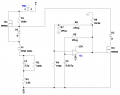
Here's a sim of the post #12 circuit, which assumes the +V source is half-wave rectified 120V RMS 60Hz.
Each 1/2 sec button press (at S1) results in a train of pulses through coil L1. The leading pulse of each train exceeds 30mA for at least 5mS.
The op-amp and its associated components do nothing useful and do not switch on M2.
Edit: R8 and M2 gate connections in the above sim are wrong. R8 should go to ground instead of -12V. Mr gate should go to op-amp output instead of to R8.
Don't use the DAC. Use the MCU to control turning your 60Hz signal generator on off, with a double-OpAmp and tuning tank circuit to generate the 60Hz pure self-sustaining sine wave, and draw the 30mA from a power-supply, not from the GPIO pin.
If you have to use the DAC is this homework? Harmonics?
Don't use the DAC. Use the MCU to control turning your 60Hz signal generator on off, with a double-OpAmp and tuning tank circuit to generate the 60Hz pure self-sustaining sine wave, and draw the 30mA from a power-supply, not from the GPIO pin.
If you have to use the DAC is this homework? Harmonics?
I disagree, sorry. Please look closer. It's not so much a high-side switch as a voltage follower. The op-amp square wave oscillator drives NMOS M2 on to sink L1's current via D1 and D2, with M2 off R1 and M1 source current to L1. Because of C1 the source and sink currents will eventually balance out.
 Facebook
 Google
 GitHub
 Linkedin