How to find out the voltage increased between two circuits

Thread Starter

tuan.le007

Joined Nov 29, 2016
46
upload_2016-12-15_10-35-37.png


Hello,
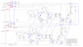
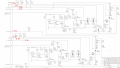
I have two circuits above. I am trying to figure out why pin 40 (A1) is reading 2.7V vs pin 39, 2, 1.

I suspect that its probably the Transistor is bad but I don't remember how to check for the transistor if its bad or not?

Do I do this with the power on or off?

I have check the resistors and they all seems okay (right value). I also checked the CAP for short but there's no short.

The only other thing I can think of is the power, but I am sure the powers are there since I am receiving 2.7V out of pin 40 (J1-5).

I have checked all the diodes and they seems okay too.
Can someone tell me where to check next?
thanks
 

Attachments

AlbertHall

Joined Jun 4, 2014
12,625
No clue there then.
Can you measure the base, emitter and collector voltages of Q6, Q7, Q13 and Q14. Also the voltage at the cathodes of VR1 and VR2.
I do not understand the circuit on the collectors of those transistors - as drawn it doesn't seem possible!
 

Thread Starter

tuan.le007

Joined Nov 29, 2016
46
thanks for your advice!
I measured the base/emitter/collector and found that Q14 is lower than the rest.
one reads 0.6V and one reads 0.2v so I believe its a bad transitor.
I will remove it and find out if it works!
thanks!
 

ScottWang

Joined Aug 23, 2012
7,501
According to the circuis then the voltages of 8 pins should be comparing as:
1. pin-12(3.7V) comparing with pin-23(3.7V).
2. pin-1(2.4V) comparing with pin-39(2.3V) ... 0.1V
3. pin-2(2.4V) comparing with pin-40(2.7V) ... 0.3V
4. pin-6(3.8V) comparing with pin-28(4.1V).... 0.3V
5. pin-3(14.1V) comparing with pin-35(14.1V)

So there are 3 pins are different, the pin-2 and pin-39 in some application maybe is ok, but the pin-40(2.7V) is higher than pin-2(2.4V) 0.3V, and the pin-28(4.1V) is also higher than pin-6(3.8V) 0.3V.

You said that you already checked the resistors, did you desolder them from the PCB?

Please measure the voltages where I used arrows to shown in the circuits.
 

Attachments

AlbertHall

Joined Jun 4, 2014
12,625
Scott, can you see where that -3.9V on the collectors of Q6, Q7, Q13 and Q14 comes from? Note the polarity of the two zeners and the electrolytics in parallel with them.
 

Thread Starter

tuan.le007

Joined Nov 29, 2016
46
I used a DMM to measure the voltage across the points you mentioned.

upload_2016-12-16_11-3-43.png

the red font is the value using an osscillascope.
the green font is the value using a dmm (Vdc).

I only see that at Q5 and Q12 is where the major different in voltage drop.
I have tried replacing Q12 but it doesn't seems to fix the problem.
Maybe I am re-using Q12 from old component?
 
Top