Facebook
 Google
 GitHub
 Linkedin
Hi all,
I think this is very simple but I have thought about it too much and confused myself....
I need to test a project that has a CT input. For practicality reasons i would like to make a test fixture with knows that set the faked AC current.
I thought this would be easy, just connect an AC/AC transformer type wall wart with a low voltage output to a potentiometer and connect the resulting variable AC voltage to the CT input, right?
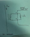
But then i started thinking about it ....There is a 1R burden resistor on the CT input, and the CT itself is a current source that drives a voltage across that resistor representative of the current.
So if i connect a variable AC voltage in place of the CT, it has to be able to drive enough current to raise the voltage over that 1R resistor... but i wanted to use say 100k pots and have effectively tiny power used everywhere....but then again when the real CT is in place there is not significat power being dissipated - the burden resistor is a small SMD part!
Where am i going off the rails on this thinking???
I think this is very simple but I have thought about it too much and confused myself....
I need to test a project that has a CT input. For practicality reasons i would like to make a test fixture with knows that set the faked AC current.
I thought this would be easy, just connect an AC/AC transformer type wall wart with a low voltage output to a potentiometer and connect the resulting variable AC voltage to the CT input, right?
But then i started thinking about it ....There is a 1R burden resistor on the CT input, and the CT itself is a current source that drives a voltage across that resistor representative of the current.
So if i connect a variable AC voltage in place of the CT, it has to be able to drive enough current to raise the voltage over that 1R resistor... but i wanted to use say 100k pots and have effectively tiny power used everywhere....but then again when the real CT is in place there is not significat power being dissipated - the burden resistor is a small SMD part!
Where am i going off the rails on this thinking???
")