Facebook
 Google
 GitHub
 Linkedin
Hey,
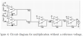
I need some help with a couple of circuits that I built. The circuits together are supposed to function as an analog calculator. I realize that analog computers can not be 100% accurate, but I wanted to test how inaccurate an analog calculator really is. So I built the following circuits:


I tested the accuracy of Vout in these circuits in the following manner:
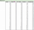
- I held V2 at a constant voltage (1,00V)
- I varied V1 from 0 to 11V (with the exception of subtraction where I varied it from -11V to 11V)
- I measured Vout and notated the deviation from the expected answer.
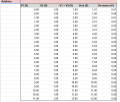
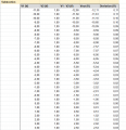
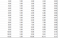
You can see my measurements in this spreadsheet:
https://docs.google.com/spreadsheets/d/1x4-jEH6Oq_Z8XAO9q5Yww91Y0tWsc4h5c5UrkOKvK2Q/edit?usp=sharing
There's multiple things that caught my attention here:
- With addition and subtraction, it seems that the higher V1 is, the higher the deviation is. Addition and subtraction are relatively pretty accurate.
- With multiplication it's a little bit more complicated. It seems that until V1 reaches 7V, the deviation increases quite linear. However, after 7V, the measurements stop making sense for me. Firstly, when measuring the voltage, Vout would continuously vary within a range of around 0.5V. This made it hard to measure Vout since in one second, it could change a lot, unexplainably.
- The results for divison hardly allow any logical reasoning for me, since the deviation values seemed completely random. The same behaviour as with the multiplication circuit has been noted; Vout would continously vary within a (although smaller) range of around 0.15V. This made it hard to measure Vout exactly.
So my question is, what could cause this behaviour? For subtraction and addition I feel like it has to do with a positive Common Mode amplification factor. The common mode signal increases if (V1+V2) increases, so that would make sense. It would also explain the linear relationship between V1 and the deviation. Is this a correct analysis?
However, for multiplication and division I have no clue what causes these fluctuations and deviations. It would help a lot if someone could explain this behaviour.
If you have any questions regarding my circuit or the measurements, please let me know. Thanks in advance!
I need some help with a couple of circuits that I built. The circuits together are supposed to function as an analog calculator. I realize that analog computers can not be 100% accurate, but I wanted to test how inaccurate an analog calculator really is. So I built the following circuits:
I tested the accuracy of Vout in these circuits in the following manner:
- I held V2 at a constant voltage (1,00V)
- I varied V1 from 0 to 11V (with the exception of subtraction where I varied it from -11V to 11V)
- I measured Vout and notated the deviation from the expected answer.
You can see my measurements in this spreadsheet:
https://docs.google.com/spreadsheets/d/1x4-jEH6Oq_Z8XAO9q5Yww91Y0tWsc4h5c5UrkOKvK2Q/edit?usp=sharing
There's multiple things that caught my attention here:
- With addition and subtraction, it seems that the higher V1 is, the higher the deviation is. Addition and subtraction are relatively pretty accurate.
- With multiplication it's a little bit more complicated. It seems that until V1 reaches 7V, the deviation increases quite linear. However, after 7V, the measurements stop making sense for me. Firstly, when measuring the voltage, Vout would continuously vary within a range of around 0.5V. This made it hard to measure Vout since in one second, it could change a lot, unexplainably.
- The results for divison hardly allow any logical reasoning for me, since the deviation values seemed completely random. The same behaviour as with the multiplication circuit has been noted; Vout would continously vary within a (although smaller) range of around 0.15V. This made it hard to measure Vout exactly.
So my question is, what could cause this behaviour? For subtraction and addition I feel like it has to do with a positive Common Mode amplification factor. The common mode signal increases if (V1+V2) increases, so that would make sense. It would also explain the linear relationship between V1 and the deviation. Is this a correct analysis?
However, for multiplication and division I have no clue what causes these fluctuations and deviations. It would help a lot if someone could explain this behaviour.
If you have any questions regarding my circuit or the measurements, please let me know. Thanks in advance!
Attachments
-
 120.6 KB Views: 7