how to detect the zero crossing for an AC input signal

Thread Starter

Fanfire174

Joined Mar 13, 2018
240
Hi,
If you use the 'zc' pulse you would not use the compare function.

You would use PORTB.0 on change interrupt.
E
Is it the code you are referring
Code:
unsigned char FlagReg;
sbit ZC at FlagReg.B0;

void interrupt(){
     if (INTCON.INTF){          //INTF flag raised, so external interrupt occured
        ZC = 1;
        INTCON.INTF = 0;
     }
}

void main() {
     PORTB = 0;
     TRISB = 0x01;              //RB0 input for interrupt
     PORTD = 0;
     TRISD = 0;                 //PORTD all output
     OPTION_REG.INTEDG = 0;      //interrupt on falling edge
     INTCON.INTF = 0;           //clear interrupt flag
     INTCON.INTE = 1;           //enable external interrupt
     INTCON.GIE = 1;            //enable global interrupt

     while (1){
           if (ZC){ //zero crossing occurred
              PORTD.B0 = 1; //Send a 1ms pulse
              delay_ms(1);
              PORTD.B0 = 0;
              ZC = 0;
           }
     }
}
here is another
Code:
void main()
{
  TRISC = 0; //Configure PORTC as ouput

  TRISA.RA0=1; // Configure as input pin for negative input of Comparator 1
  TRISA.RA1=1; // Configure as input pin for negative input of Comparator 2
  TRISA.RA2=1; // Configure as input pin for positive input of Comparator 1
  TRISA.RA3=1; // Configure as input pin for positive input of Comparator 2
  TRISA.RA4=0; // Configure as output pin for output of Comparator 1
  TRISA.RA5=0; // Configure as output pin for output of Comparator 2

  CMCON=0x05; // 'Two Common Reference Comparators with Outputs' Mode

  while(1)
  {
    PORTC.F0 = CMCON.C2OUT; // Assigning output of comparator 2 to RC0
    PORTC.F1 = CMCON.C1OUT; // Assigning output of comparator 2 to RC1
    Delay_ms(100);
  }
}
I am totally confused by looking some links. I don't know which link to follow or which interrupt set for project external interrupt or comprator interrupt?
 
Last edited:

MaxHeadRoom

Joined Jul 18, 2013
30,717
I want to determine time at every zero crossing for 5V AC input signal using the PIC micro-controller.in my search i found that I have to use interrupts to detect when the sine wave crosses zero. when interrupt will enable, timer will be start, it will run untill the interrupt become disable stop the timer and store time value in variable repeat this process continousely
Does anyone know how to detect the zero crossing for an input signal?
As I previously shown the zero crossing detector in the Fairchild AN-3006 works fine as per the graph in fig4, there are also similar methods out there.
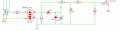
Also I have used this method below, if you need isolation, place an opto in the 2n7000 drain.
And you can eliminate the 5vdc source components.
Max.


upload_2018-4-13_9-8-32.png
 

Thread Starter

Fanfire174

Joined Mar 13, 2018
240
Interrupt on change can be a bit tricky. Better to use RB0/INT.
12.10.1
INT INTERRUPT
External interrupt on the RB0/INT pin is edge triggered,
either rising, if bit INTEDG (OPTION_REG<6>) is set,
or falling, if the INTEDG bit is clear. When a valid edge
appears on the RB0/INT pin, flag bit INTF
(INTCON<1>) is set.
which interrupt i need to set external interrupt , intererrupt on change or comprator interrupt
 

LesJones

Joined Jan 8, 2017
4,509
I think measuring the time of the zero crossings is the easy part. I would set timer 1 to be running at a suitable frequency and enable CCP1 interrupt. I would connect the zero crossing to CCP1 input. At every zero crossing the current count of timer 1 would be captured and an interrupt generated. The interrupt routine would save the captured count and subtract the last captured value from the current count. This would give the number of counts between the last two zero crossings. This would then be converted into the format that you wanted to store it. Storing the data will be the big problem as you will have 100 (Or 120) readings every second. You have a few options. 1 storing the readings using registers. This is fast but you will very quickly run out of space. The other three options are using internal EEPROM, Using an external EEPROM or using program memory like EEPROM. All these three options involve disabling interrupst while writing data so you are likely to miss readings. A better way to capture the readings may be to output the readings to the serial port and capture them using a terminal emulator program running on a PC.

Les.
 

Thread Starter

Fanfire174

Joined Mar 13, 2018
240
I think measuring the time of the zero crossings is the easy part.
Les.
there are difeernt information provided by members But I am not getting which interrupt will be use ?

PIC 16F877A interrupt sources :
  • External
  • Comparator
  • CCP1
It will batter someone tell me the interrupt that I need to use
 

LesJones

Joined Jan 8, 2017
4,509
The interrupt that you use depending on the way you choose to measure the time interval between zero crossings. The way I suggested in post #24 you would just use the CCP1 interrupt. There is only one entry point to the interrupt service routine on a PIC16F877. If you have more than one interrupt source enabled the first thing you need to to in your interrupt service routine is to sort which interrupt source triggered the interrupt.

Les.
 

ebp

Joined Feb 8, 2018
2,332
What kind of accuracy is required?

Zero crossing detectors are subject to jitter due to noise and waveform distortion. Some amount of timing skew will result from using a transformer. Interrupt service timing uncertainty can be substantial if not very carefully evaluated and the entire system managed to optimize it. Ordinary microcontroller clocks are generally pretty sloppy and unsuitable for precision timing. It all comes down the requirements.

I've use 8-bit PICs to manage timing of firing of SCRs in three-phase controlled bridge rectifiers and produced very satisfactory results using an inexpensive crystal, quite simple circuitry and polling of a zero crossing signal derived from a transformer. If the intent is to try to precisely measure mains frequency to detect something like the recent frequency error problem in Europe, any attempt to use an off-the-shelf low cost microcontroller board is pretty much doomed to failure.
 

Thread Starter

Fanfire174

Joined Mar 13, 2018
240
Is it similar code to measure time of input signal ?
Code:
sbit LCD_RS at RB1_bit;
sbit LCD_EN at RB2_bit;
sbit LCD_D4 at RB3_bit;
sbit LCD_D5 at RB4_bit;
sbit LCD_D6 at RB5_bit;
sbit LCD_D7 at RB6_bit;

sbit LCD_RS_Direction at TRISB1_bit;
sbit LCD_EN_Direction at TRISB2_bit;
sbit LCD_D4_Direction at TRISB3_bit;
sbit LCD_D5_Direction at TRISB4_bit;
sbit LCD_D6_Direction at TRISB5_bit;
sbit LCD_D7_Direction at TRISB6_bit;

long t2=0; //2nd capture edge (Low)
char periodData[20];
char text[7];
int doub;
int i=0;
double MPH;
void hardwareInit()
{
  CCP1CON = 0x05; // Capture rising edge (101)
  CCP2CON = 0x04; // Switch edge to falling
TRISC.B2 = 1; // CCP1 pin - RC5 set to input
TRISC.B1 = 1; // CCP1 pin - RC5 set to input
TRISB.B0= 0;
PORTB.B0=0;
PIE1.B2 = 1; // .. Enable CCP1 interrupt CCP1
PIE2.B0 = 1; // ... Enable CCP2 interrupt
PIR1.TMR1IF=0; // Enable timer 1 overflow
INTCON.PEIE = 1; // ...And global & peripheral interrupts
INTCON.GIE = 1;
T1CON= 0b00000000;
T1CON.TMR1ON= 0; // turn on the timer1
TMR2IE_bit=1;
}

void interrupt() {
if(PIR1.CCP1IF==1)
{
T1CON.TMR1ON= 1; // turn on the timer1
TMR2IE_bit=1;
PIR1.CCP1IF = 0; // Reset flag
PIE1.B2 = 0; // .. Enable CCP1 interrupt CCP1
}
if(PIR2.CCP2IF==1)
{ // Flag for 2nd capture (low)
PIE2.B0 = 0; // ... Enable CCP2 interrupt
T1CON.TMR1ON=0; // turn off the timer1
TMR2IE_bit=0;
t2 = t2 + (TMR1H<<8)|(TMR1L); // Store values for 2nd capture
MPH = (5007999/t2); // MPH calculation
TMR1H=0x00;
TMR1L=0x00;
PIR2.CCP2IF = 0; // Reset flag
PIE2.B0 = 1; // Reset CCP interrupt
PIE1.B2 =1;
t2=0;
}
if (TMR1IF_bit==1)
{
t2 = t2+1023;
TMR1H=0x00;
TMR1L=0x00;
TMR1IF_bit==0;
i++;
T1CON.TMR1ON= 1; // turn on the timer1
}
}
void main(){
Lcd_Init(); // Initialize LCD

Lcd_Cmd(_LCD_CLEAR); // Clear display
Lcd_Cmd(_LCD_CURSOR_OFF); // Cursor off

hardwareInit();
T1CON.TMR1ON=0;
while(1)
{
doub = floor(1/MPH * 1000);
intToStr(doub, periodData); // Output
intToStr(i, text); // Output
Lcd_out(1,1,"Period=");
Lcd_Out(1,8,Ltrim(periodData));
Lcd_out_cp("ms");
Lcd_out(2,1,text);
}
}
 

Thread Starter

Fanfire174

Joined Mar 13, 2018
240
For a 5VAC signal into a microcontroller, AC-couple the signal through a series capacitor and bias the signal to ½Vcc, i.e. at 2.5V.
Use an analog comparator with a reference set to 2.5V.
Instead of starting and stopping a timer, use the input capture function of the timer module.
I have 9v steup down transformer. it give 9v AC. Is it possible to use inbuilt comparator of PIC16f877a for zero crossing?
 
Top