How to derive H bridge driver pulses at 1 pulse per minute ?

Thread Starter

cornishlad

Joined Jul 31, 2013
242
Following on from my post of a few days ago ( driving (inputting) the L9110s H-Bridge ) I was a tad optimistic when I said it was now working fine.
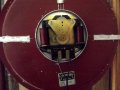
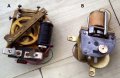
Brief re-cap. I have a pulse, 1/3sec duration @ 2 ppmin, debounced, coming from a pendulum master clock, driving a clock dial that I thought needed a pukse every 30 sec of alternate polarity. It did work - but the clock dial was moving at twice the correct speed. The clock motor , which was an ebay buy and is new to me, obviously requires a pulse every minute of alternate polarity.
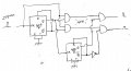
I've tried every thing I can think of to obtain this using the same chips, but using the other half of the 4013. I couldn't do it.
So.. the question. I don't have a 4081, but before I order one, would this circuit work ? ie..The original 1/3sec duration pulses @ 30 sec intervals are needed to drive the L9110 hbridge every minute and alternate polarity..EG57_ 157.png
 

Attachments

Last edited by a moderator:

ericgibbs

Joined Jan 29, 2010
18,849
h C,
This is what LTS shows, check my circuit for accuracy.
E
Note 0 to 360 seconds
Notice the timing delay Glitch pulse.!

EG57_ 159.png
 

Thread Starter

cornishlad

Joined Jul 31, 2013
242
Eric.. That's great.. and thank you for taking the trouble to do that.
There are some ifs about the result. Can I assume the second of each pair of pulses P1 and P2 are the glitches ?
Is it possible that they are so short that the H bridge would not respond..(big if)
However, assuming the later it looks like P2 pulses are not in the correct phase for even minute stepping although the clock would overall keep time ?
I beg your indulgence as I learned my electronics in the early 1960's when glass things reigned supreme.. My old brain is at it's limit figuring this stuff..
Another thought... could the phase error be eliminated if the final AND gates received pulses from Q & Qbar rather than both from Q ? Roger
 

ericgibbs

Joined Jan 29, 2010
18,849
hi C,
The CD4000 series of CMOS gates are slow, so their internal delays can cause glitches as they switch. These glitches will most likely trigger the H bridge IC inputs.

E

Update:
Why do you think a 0.33Sec pulse would drive the H bridge IC.
This is what the datasheet says, ref image.
E

@cornishlad

Please a post a sketch showing the required pulses, duration and rate, I will try LTspice simulation.

EG57_ 160.png
 
Last edited:

crutschow

Joined Mar 14, 2008
34,432
Here's the LTspice simulation of a simplified circuit that I think does what you want:
Each pulse occurs once every two minutes with alternate phase pulses occurring once a minute.
The FF is triggered on the clock falling edge to eliminate output glitches from the race condition (the FF's change state at the end of the pulse instead of the beginning), and uses one D-FF and one NOR-gate package.

1667184768767.png
 
Last edited:

Thread Starter

cornishlad

Joined Jul 31, 2013
242
Ther's a lot there for me to get my head around.. Thanks.. I come back tomorrow when I've absorbed the comments.. R
 

Thread Starter

cornishlad

Joined Jul 31, 2013
242
First off I'll reply to Eric but thanks to lowQCab and crutshow for responding..will study and reply next ..
Eric. I think that possibly, due to your two replies I may have got to grips with this a lot better. I wish I had the ability to work the software that you've used to test and draw the circuit so nicely !
Firstly, I know that the driver puses from the earlier circuit will work ok (with the L9110 H bridge) as they drove the clock ok ,but at twice the wanted rate. (see https://forum.allaboutcircuits.com/threads/driving-inputting-the-l9110s-h-bridge.189883/post-1773931 )
I've realised that regardless of how the H bridge reponds to glitches, or even multiple versions of P1, the "motor" itself will not respond until a timely P2 pulse arrives to trigger the opposite polarity output.
But it did make me think more deeply about H bridges. I have limited experience of them but had come across a 40 year old design in a commercial clock that used discreet transistors. This design would change o/p polarity on arrival of the FIRST P1 pulse and ignore further P1 pulses until a P2 arrived (bi-stable on i/p)
I didn't think the L9110 worked that way. ? it seemed to me to repond to every P1 pulse. ie. outputing polarity x for the duration of P1 each time if more than one P1 pulses arrived before P2 (and vice versa) I may be wrong !
But I imagine it's also possible to design an H bridge that would only output polarity x once (for the duration of P1) and ignore glitches or genuine extra spurious P1 pulses.
I think the following small change to the circuit in the post above may produce the required output drive, with no phase error - but still with glitches. but needs and extra inverter. (and not as elegantly as crutschow's) back later.
 

Attachments

ericgibbs

Joined Jan 29, 2010
18,849
hi Roger,
The timing interval is wrong on the new circuit.
E
On the 2nd smaller image, I have cleaned off any glitch pulses to make it clearer for you to see.
EG57_ 162.png
 

Attachments

Last edited:

Thread Starter

cornishlad

Joined Jul 31, 2013
242
@ Eric.. Thanks for doing the sim. Later I'll try to fathom why it's still no good - but meantime give up on trying to design it myself :)
@ LowQCab. Thanks for posting that but I'm afraid its beyond me to get the sollution from it.
@ crutshow.. The timing diagram is the holy grail !! I will ponder on how it works, but will build it and use it when I get the NOR gate. Thank you again for taking the trouble to design it.
I'll report back here if it doesn't take to long to get the project finished.. Roger
 

crutschow

Joined Mar 14, 2008
34,432
The timing diagram is the holy grail !! I will ponder on how it works,
To help with that, below is the simulation with the two FF Q outputs also shown:
It might be easier to understand if you view the NOR gate as an inverted input AND gate (i.e. all inputs must be low to give an output high).
(It can also be helpful at times to view a NAND as an OR with inverted inputs).
And note that the FF's are changing state at the fall of the clock input pulse.

1667237930246.png -------1667239739662.png
 
Last edited:

LowQCab

Joined Nov 6, 2012
4,072
What needs to be known is the exact requirements / specifications, etc.,
of the mechanism in the Clock.

Then anyone here could design a workable Circuit.

So far, my vague interpretation of how it operates is that it requires a
"Positive" input for one full Minute,
then a "Negative", ( or no Input ), Input for one full Minute ..... Repeat, Repeat, Repeat, ........

I certainly could be wrong, or may have mis-understood something,
but this sequence scenario seems highly unlikely to me.

My best blind "guess" would be that it requires maybe a ~100ms Pulse, every 59.9 seconds.
.
.
.
 

crutschow

Joined Mar 14, 2008
34,432
Thank you again for taking the trouble to design it.
No trouble at all. :)
Answering questions and designing circuits for various requests on several electronic forum websites, is sort of my retirement hobby.
When designing I try to follow a quote attributed to Einstein: "Make it as simple as possible, but no simpler".
 

Thread Starter

cornishlad

Joined Jul 31, 2013
242
Background and purpose. In the first half of the 20th century, before quartz clocks kept near perfect time and cost next to nothing, good timekeeping was achieved in large building with a chain of slave clocks fed by a high quality electric master clock with a one second pendulum.
The master clocks often had a simple armature operated mech that advanced evry 1/2 minute. On the continent the 1 minute steppers were common. Early systems used unidirectional pulses.
These dials were often noisy (they clicked) and some users required silent slave clocks such as in broadcasting studios. The 'motors' of alternating pulse drive sytem filled the bill. These systems usually used a parallel distibution circuit which was not so prone to complete failure if the series loop system became O/C
A hobby of mine is collecting and restoring/running such clocks. If any of you are interested I'll post a couple of pictures of some slave mechanisms including the one which is the focus of this inquiry.
I've also built a couple of similar clocks and if you really want to, can see them here ;-) : http://www.rogerj.co.uk/clock.htm
 

Janis59

Joined Aug 21, 2017
1,849
Probably here is (and especially if the accuracy takes a count) place where ARM processor may do a better job than thick bunch of IC. Just take for 0.99 cents one Cheeneeze "Arduino compatible" and bit witchcraft on coding.
 

Thread Starter

cornishlad

Joined Jul 31, 2013
242
Janis.. LOL.. I've been told that many times over the years! I did buy an Arduino and a book but never managed to get my brain to work with programming.. And.. I actually like hardware.. R
 

Thread Starter

cornishlad

Joined Jul 31, 2013
242
I have a 4025 and have made a start breadboarding your (crutshow) circuit. It maybe next week b4 I can finish and test.
Meantime here's a photo of the 1 minute, alternate pulse motor, the subjuect of the thread. The other picture has at A a unidirectional drive, solenoid type 30 sec stepper and at B a Gents alternate drive 30 sec stepper.
 

Attachments

tonyStewart

Joined May 8, 2012
131
First off I'll reply to Eric but thanks to lowQCab and crutshow for responding..will study and reply next ..
Eric. I think that possibly, due to your two replies I may have got to grips with this a lot better. I wish I had the ability to work the software that you've used to test and draw the circuit so nicely !
Firstly, I know that the driver puses from the earlier circuit will work ok (with the L9110 H bridge) as they drove the clock ok ,but at twice the wanted rate. (see https://forum.allaboutcircuits.com/threads/driving-inputting-the-l9110s-h-bridge.189883/post-1773931 )
I've realised that regardless of how the H bridge reponds to glitches, or even multiple versions of P1, the "motor" itself will not respond until a timely P2 pulse arrives to trigger the opposite polarity output.
But it did make me think more deeply about H bridges. I have limited experience of them but had come across a 40 year old design in a commercial clock that used discreet transistors. This design would change o/p polarity on arrival of the FIRST P1 pulse and ignore further P1 pulses until a P2 arrived (bi-stable on i/p)
I didn't think the L9110 worked that way. ? it seemed to me to repond to every P1 pulse. ie. outputing polarity x for the duration of P1 each time if more than one P1 pulses arrived before P2 (and vice versa) I may be wrong !
But I imagine it's also possible to design an H bridge that would only output polarity x once (for the duration of P1) and ignore glitches or genuine extra spurious P1 pulses.
I think the following small change to the circuit in the post above may produce the required output drive, with no phase error - but still with glitches. but needs and extra inverter. (and not as elegantly as crutschow's) back later.

TL;DR (too long , didn't read) . The whole threads... But your glitch can be eliminated with an xx microsecond RC delay from Clk to U2,U3 to offset the async delays on the rising edge in the two FF's. But the 3 input NOR improved design also works.
 
Top