How to convert positive signal to ground?

sghioto

Joined Dec 31, 2017
8,737
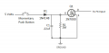
As far as the switch circuits are concerned there are several options as already presented. I'm confident the circuit posted in #32 will work although some component values may need to changed. This circuit is designed for the toggle and maintained push button switches. The other switches and can use the same 2N7000 transistor with a slight design difference.
 

Thread Starter

Starbase101

Joined Apr 27, 2021
21
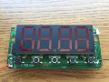
So focusing on just the timer and its momentary switches, this doesn't fit in my project's panel with the tactile switches where they are, and I have a different (illuminated) button style I'd rather use instead.

Timer.JPG

You can see they all share a common -3V ground line, indicating they're switching on the positive side. My plan is to simply remove these switches from the board and instead wire the board connections to larger panel-mount illuminated momentary pushbutton switches. If it were just that then it would be simple, but I though it would be fun to have sound-effect "beeps" triggered when pressing the buttons. But the Adafruit board takes grounded triggers, which is the opposite of how these buttons operate.
 
Last edited:

Papabravo

Joined Feb 24, 2006
22,105
English is the only language I speak. I thought the questions were clear, especially with the schematic - pulling low trigger inputs on a sound board from 3 different types of switches which aren't switching a ground signal. Then the discussion shifted to potential circuit noise from the motor (which is just a small DC turntable motor) and stabilizing power inputs to the sound board, which are great topics that I would be interested in knowing more about but just one thing at a time please.
No need to get huffy. because "convert a positive signal to ground" is hardly a commonly understood phraseology. If it takes a few tries to communicate your intent, a bit of patience will go a long way. What will get you ignored is to cop an attitude.
 

Papabravo

Joined Feb 24, 2006
22,105
So focusing on just the timer and its momentary switches, this doesn't fit in my project's panel with the tactile switches where they are, and I have a different (illuminated) button style I'd rather use instead.

View attachment 237042

You can see they all share a common -3V ground line, indicating they're switching on the positive side. My plan is to simply remove these switches from the board and instead wire the board connections to larger panel-mount illuminated momentary pushbutton switches. It were just that then it would be simple, but I though it would be fun to have sound-effect "beeps" triggered when pressing the buttons. But the Adafruit board takes grounded triggers, which is the opposite of how these buttons operate.
Is the terminal labeled "3V-1" at GROUND or at "-3V ground", whatever that means?
 

Thread Starter

Starbase101

Joined Apr 27, 2021
21
I didn't mean to come across as huffy or having an attitude, sorry. I will place an order for the ULN2803A as well as the parts shown in post #32. If the ULN2803A works by itself then great, otherwise I'll assemble the other parts on a breadboard and try that out. If the second option works with each of the 3 switch types then I'll place a second order for the parts to do the remaining switches.

Should I get a Schottky diode as well for the motor, or can that be resolved by instead powering it from a 7805 5V regulator? (A change from 3V to 5V on the motor is negligible and in my opinion it rotates too slowly at 3V anyway.)

Do I get the two capacitors for the FX Mini power input as well, or are they a little redundant/overkill since all the DC voltages are regulated anyway?

Anything else I should consider including for making the most of shipping costs?

Thanks!
 

sghioto

Joined Dec 31, 2017
8,737
You can test for yourself if the ULN2803 will work before buying if you want. I can show you a simple circuit to simulate its output.
 

AnalogKid

Joined Aug 1, 2013
12,232
If the ULN2308 won't work I suggest using a FET.
That doesn't meet this requirement:
Pressing a momentary switch too quickly and not having any sound output would defeat the whole purpose of investing in a "coolness" feature. A high resistor and a cap are vague so I would like to ask for help with guaranteeing longer than 125ms pulses between the ULN2803A and the FX Mini.
What will work is a 2-gate monostable. This eliminates the need for a differentiator on the input. However, these circuits are not logically inverting. That is, if the input is a positive-going pulse, so will be the output. This is because the circuit needs positive feedback, requiring that the input and output be in phase.

The solution is an inverter on the output. We now have four chips:
2 - Quad NOR gate chips, one NOR gate per monostable circuit.
8 - Capacitors, one per circuit.
1 - Resistor network, 9 resistors and one common pin.
2 - Octal inverting buffers or transparent latches, one chip for 8 inverters to complete the 8 monostables, and one chip to invert the 8 monostable outputs.

ak
 

Thread Starter

Starbase101

Joined Apr 27, 2021
21
Yeah, I figured I'd need an inverter for reversing the signal to the sound board's trigger requirement of ground. Simply passing the switch's signal through an inverter probably isn't enough though, especially for the toggle and maintained switches which remain in a "pressed" state until pressing the switch again. I apologize, but I am just getting overwhelmed by the variety of solutions. It seemed so simple in my head, press a switch and some component(s) generate a ground pulse (once) for at least 125ms, regardless of whether that switch is momentary, maintained, or toggle. What is seeming simple in your minds is baffling to me (as I'm sure would be the same for things which are simple to me that another person has no experience with).
 

KeithWalker

Joined Jul 10, 2017
3,614
The picture of the timer in post #42 shows the momentary switches all connected to the negative side of the 3V supply. That is circuit common (or ground) in your circuit diagram. When a switch is pressed, it connects a pin on the chip to circuit ground.. You say that "they're switching on the positive side" which is ambiguous and confusing. They are simply switching to ground which is the same type needed to switch the trigger lines in the sound card.

You can not use a single switch contact to work in both modules at the same time. That will cause problems. The way around that is use non-inverting buffers (HEF4050B). A momentary switch to ground connects to two buffer inputs with a pull-up resistor. One output is connected to a sound trigger pin and the other to a timer input.

A diode is necessary across the motor whichever supply you connect it to and the capacitors are not overkill. Without these, you have very little chance of getting it to work.

Again, I will mention that pulse delays are not necessary on either device input. They have built-in de-bounce software.

I think I have answered your questions in a clear and concise way. If there is something you don't understand, please ask.
 
Last edited:

Thread Starter

Starbase101

Joined Apr 27, 2021
21
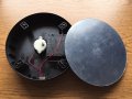
The product I've opened up to run off an AC/DC adaptor instead of batteries already has a diode inside. So, probably just leave that as-is and simply replace the slider switch with a toggle switch and change the 3V battery supply to a regulated 5V supply (for slightly faster rotation)?

UVbox6.JPG
 

KeithWalker

Joined Jul 10, 2017
3,614
That diode appears to be only switched in series with the motor terminals when the switch is moved to the right. Is it used to reduce the motor speed? You still need one directly across the motor with its cathode (banded end) connected to motor+. If you use a different supply, make sure it can handle the motor start-up current surge.
 

Thread Starter

Starbase101

Joined Apr 27, 2021
21
Yes, the slide switch has 3 positions, on-off-on, with the two on positions being different motor speeds. This is not a feature I'm interested in, so a simple toggle switch will turn the motor on/off. I guess I'll look around for a Schottky diode to use here. Thanks.
 

KeithWalker

Joined Jul 10, 2017
3,614
Yes, the slide switch has 3 positions, on-off-on, with the two on positions being different motor speeds. This is not a feature I'm interested in, so a simple toggle switch will turn the motor on/off. I guess I'll look around for a Schottky diode to use here. Thanks.
If you don't need two speeds, then use that diode directly across the motor. It will be able to handle the back EMF.

In your diagram, you show the push switches connecting the trigger inputs to +3V. That will not work and will probably damage the inputs. They should switch the inputs to ground to work correctly.
 

Ya’akov

Joined Jan 27, 2019
10,276
Just a point for the future. The terminology for the two options is active high vs active low. In the former case a pin works by being "pulled high", that is, connected to the positive rail while in the latter it is "pulled low"—connected to the negative rail.

It's not always necessary to pull the pins all the way to these values, some will activate at something between Vcc/2 and Vcc (the positive supply) and "ground" (0V), not really ground but it will also be called that.
 

atferrari

Joined Jan 6, 2004
5,020
The value of 125 ms has been mentioned many times, mostly like a requirement for the Fx Mini.

Is it pure timing or just debouncing for the button?
 
Top