How to convert positive signal to ground?

Thread Starter

Starbase101

Joined Apr 27, 2021
21
ULN2803A looks very interesting and with 8 channels, very similar to sghioto's diagram above. I understand electronics basics, but it's not my expertise. Pressing a momentary switch too quickly and not having any sound output would defeat the whole purpose of investing in a "coolness" feature. A high resistor and a cap are vague so I would like to ask for help with guaranteeing longer than 125ms pulses between the ULN2803A and the FX Mini. Maybe there exists different transistors which yield a more-ideal signal? It's not a requirement for me that they're all on one chip. Thanks.
 

MrChips

Joined Oct 2, 2009
34,974
Maybe there exists different transistors which yield a more-ideal signal? It's not a requirement for me that they're all on one chip. Thanks.
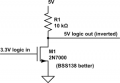
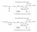
Basically, you can choose between an NPN BJT or an N-channel MOSFET.

(For demonstration purposes only. Ignore the different voltages shown in the schematics.)

1619622475113.png


1619622385500.png
 

ElectricSpidey

Joined Dec 2, 2017
3,343
You commented about the number of components in another reply...well if you want to insure coolness by only having to press the button for a very short time (125 ms is a very short time) you will need additional circuitry and things may become complex.

I suppose adding a ground to base (input) cap would provide a delay on the mom switches.
 

Thread Starter

Starbase101

Joined Apr 27, 2021
21
I have lots of space for components, just thought it might be a simple thing of generating a ground pulse trigger from positive switch signals. If the number of components gets too high, it just means I'll layout a custom PCB rather than using a generic project board. Reliability is more important than being frugal with the number of components. Well, that and not burning the house down when powering it up! I guess what I'm hoping for here is a shopping list and how to connect it up. Thanks
 

AnalogKid

Joined Aug 1, 2013
12,202
It sounds like you need a guaranteed minimum output pulse width that is longer than a person's reaction time on a switch. This means you need a true monostable circuit, one that puts out a fixed pulse width no matter if the input signal is longer or shorter. The classic form for this is two transistors, or two 2-input NAND or NOR gates, or two sections of hex inverter plus a diode. Per output. Post 19 shows 8 input circuits, so that's 16 active elements. There are many chip combinations that can do this. Does this sound like something you can handle?

ak
 

Thread Starter

Starbase101

Joined Apr 27, 2021
21
As long as it's English and not "Greek" I can handle it. Like I said, I'm not an electronics specialist - I know enough to get by, but not enough to figure out how to make this work. With a labeled schematic I can get the parts, say from Digi-Key or such, and put together a board on my own. I'm just needing enough detail to buy the parts and know how they're to be connected.
 

ElectricSpidey

Joined Dec 2, 2017
3,343
Here this may work...but before you try it you should talk to Adafruit and be sure a Darlington will pull the triggers low enough, if not there is a MOSFET alternative. (TBD62083APG)

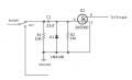
This circuit for the mom switches should work provided the resistance of the switches is low enough to charge the small cap in a short time.

AAC_FX.jpg

I didn't include any component values...I'm sure with some assistance you can figure them out. (simple RC calculations)

The FX Mini isn't real fussy about the pulse length as long as it's longer than 125ms and ends before the next one.
 
Last edited:

KeithWalker

Joined Jul 10, 2017
3,610
Before you spend a lot of time designing ingenious trigger pulse generators, I would suggest the you connect one of your momentary action switches to the device and try it. You will probably find that extra delay circuitry is not needed.
When the motor starts, it is going to generate a lot of noise on your 3.3V supply that will interfere with the operation of the sound chip. Connect a reverse diode across the motor terminals to protect against the back EMF. Run the wires that power the motor and its switch all the way back to the 3.3V supply terminals. Do the same with the sound board supply wires and add a 0.1uF and a 50uF capacitor in parallel across its power input terminals.Keep the wiring as short as possible, If the switches are not very close to the board, twist the wires to minimize interference pickup.
 

peterdeco

Joined Oct 8, 2019
484
I haven't followed this thread from the beginning but noticed an issue requiring the equivalent of a longer switch closure. I ran across this one time and an electrolytic across the switch worked.
 

Thread Starter

Starbase101

Joined Apr 27, 2021
21
The momentary switches close a positive circuit, and the sound triggers require a ground signal. I don't think simply connecting the momentary switches directly to the FX Mini would work.

I have a LM7805 that I could use to power the sound board and amplifier from the 12V supply instead of sharing the same 3V the timer and motor use, if that would help. I know what a diode is, but without a part number I wouldn't have any idea what to shop for.

The boards will be very close to the switches. Why two different capacitors in parallel across the sound board power inputs?
 

KeithWalker

Joined Jul 10, 2017
3,610
The momentary switches close a positive circuit, and the sound triggers require a ground signal. I don't think simply connecting the momentary switches directly to the FX Mini would work.
In the adafruit description they suggest testing the functions by simply momentarily touching a wire from an input pin to ground. You can't get a much dirtier contact than that!

[/QUOTE]
I have a LM7805 that I could use to power the sound board and amplifier from the 12V supply instead of sharing the same 3V the timer and motor use, if that would help. I know what a diode is, but without a part number I wouldn't have any idea what to shop for.
[/QUOTE]

The purists recommend a Schottky diode but for this simple application, any 1A rectifier diode (1N400x) will do the job,

[/QUOTE]
The boards will be very close to the switches. Why two different capacitors in parallel across the sound board power inputs?
[/QUOTE]

An electrolytic capacitor is good for stabilizing the supply but is not very efficient with high frequency spikes. The 0.1uF capacitor takes care of that as long as it is a ceramic capacitor.
 

Thread Starter

Starbase101

Joined Apr 27, 2021
21
They say connect an input pin to ground, not to a high signal. The same in YouTube videos, people connect the board's ground terminal to a trigger terminal for playing a sound. My switches are on the positive side rather than the ground side. This is not something I can change, since I'm using a digital timer board that's already set up a particular way and all I'm doing is replacing the momentary tactile switches with panel-mount LED pushbutton switches.

So if the two Adafruit boards run off 5V from a LM7805 connected to the 12V supply then they're not sharing a 3V line with the motor. Would a Schottky diode still be needed then across the motor terminals? Are there different types of Schottky diodes? Maybe instead connect the motor to a dedicated 5V (it will simply rotate slightly faster) and leave the Adafruit boards on 3V?

There shouldn't be any spikes at all? The power cord is being plugged into a surge protector strip and the 12VDC output is regulated. From the 12V adaptor there is another converter to 3VDC for the kitchen timer. I haven't seen anybody wiring capacitors to the FX Mini so that's why I'm asking.

I am appreciative of everybody trying to help, but what's intuitively understandable in everybody's heads while they're trying to help is sadly not making a whole lot of sense to me yet. :(
 

Thread Starter

Starbase101

Joined Apr 27, 2021
21
OK, what part of say the circuit posted in #32 do you not understand.
That you say "if ULN2308 won't work", which hasn't been tried yet. It's also unclear to me whether that circuit is intended for all 3 switch types or for just one type. I don't simply have a ULN2308 here waiting for a project, so if I place an order for one, connect it up, and it ends up not working then I've got a chip kicking around that will probably never get used for anything, the lost shipping cost will probably be more than the chip, and so if I'm going to be waiting for something to arrive in the mail then I would hope for it to be something that will solve the circuit problem.

It's seeming like one of those scenarios asking 5 different people the same question and getting 5 different answers - which one is the best answer? I don't know. Will any of them work any better or worse than another? I don't know. Maybe the ULN2308 is a simple one-chip solution and it will work, but there seems to be some skepticism in the posts about whether or not it will work (timing issue).
 

Papabravo

Joined Feb 24, 2006
22,084
That you say "if ULN2308 won't work", which hasn't been tried yet. It's also unclear to me whether that circuit is intended for all 3 switch types or for just one type. I don't simply have a ULN2308 here waiting for a project, so if I place an order for a ULN2308, connect it up, and it ends up not working then I've got a chip kicking around that will probably never get used for anything, the lost shipping cost will probably be more than chip, and so if I'm going to be waiting for something to arrive in the mail then I would hope for it to be something that will solve the circuit problem.

It's seeming like one of those scenarios asking 5 different people the same question and getting 5 different answers - which one is the best answer? I don't know. Will any of them work any better or worse than another? I don't know. Maybe the ULN2308 is a simple one-chip solution and it will work, but there seems to be some skepticism in the posts about whether or not it will work (timing issue).
You must understand that if your requirements are ambiguous or unclear, your chance of getting a robust reliable answer are substantially diminished. If you lack the ability to experiment and try things, then you may need to consider alternative activities. We are not there with you, and cannot see what you see. If English is not you first language, then I sympathize, but that just means you need to try harder. Maybe somebody else here would understand you better in another language. Try asking that instead of struggling. Maybe we can all learn something from the exchange.
 

Papabravo

Joined Feb 24, 2006
22,084
Most of us will go to our reward with hundreds to thousands of unused components. The storage cost alone for 50 years would amount to a small fortune.
 

Thread Starter

Starbase101

Joined Apr 27, 2021
21
English is the only language I speak. I thought the questions were clear, especially with the schematic - pulling low trigger inputs on a sound board from 3 different types of switches which aren't switching a ground signal. Then the discussion shifted to potential circuit noise from the motor (which is just a small DC turntable motor) and stabilizing power inputs to the sound board, which are great topics that I would be interested in knowing more about but just one thing at a time please.
 
Top