How to convert a 3 phase ACsource (115Vrms @ 400Hz) to a DC source

Thread Starter

Sam76767

Joined Jan 2, 2017
2
Hello!

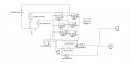
I need to design a circuit that converts a 3 phase AC source (115Vrms @ 400Hz) to a DC source. The system needs to be able to supply a DC load of 70kW (rated voltage 270V).

I have created the rectifier so far by setting 3 AC power supplies to 162V, with the 3 phases set to -120, 0 and 120, with an overall resistance of 10ohms and a capacitor with a total capacitance of 1*10^6 Henry. I have attached an image of a circuit I created with a team mate which we believe will work however we were wondering if we have missed anything or if we have messed it up completely.

Thank You!!
 

Attachments

Janis59

Joined Aug 21, 2017
1,846
1) Modern rectifiers are no longer need the shunt resistors like it was at era of selenium and germanium. That resistors are to be extirped.
2) The restifier circuit (two period full bridge) is correct, BUT the diodes for such currents are order expensiver than thyristors. Thus, if one small diode to gate may convert the thyristor to the diode, its economy of few hundreds of USD.
3) The 1 uF in the output is clearly false. Norm is 10 000 or more to avoid a massive ripple. But with such cap at the PON moment the network will get the full `short`, so the all fuses will be blown. Solutions - 1)varistor. It may never be capable to take more than ~1 kW. The resistor what is shorted when cap gets full voltage. Sorry to tell but for such current the relay will cost many thousands, so this is not appropriate over some 10 kW. Therefore for ca 100 kW there ought be used thyristors, those the same working a diode job. The classics is organize the thyristor power regulator while `cold`, what is floating toward 100% power when cap gain a full Voltage. Of course, the driving of all those bunch must be organized via optocoupler bunch, hopefully those giving a zero-voltage switching mode to avoid a fireworks on frontier.
But there is even a nicer model how to get the snake out of box without of large effort. Just make a brute parallel identical rectifier lading-up those cap via ca 1 kOhm. Take care that thyristors driving optos are getting permit to switch on just when the cap voltage is sth 80% of nominal. Say, 220/380 V European line has 535 V cap voltage, so mine elaborated 120 kW system is switching on at 465V. When the work is done by main rectifier, there is no any need to disconnect the small-one. Let it hang there, the 1 kOhm will take care of it. For my case I used 350Amp 1200V thyristor bricks and for smaller rectifier the 1N4007. How far I can see, this very simple and effective circuit is commonly unknown, but is worth to give a chance.
Last advice. Always use a bifillary wire line for any transfer of DC. Because at 300A if any igbt at the H-bridge after output will produce a sudden `needle` of say 10 nanosecond (what correspond to upper ringing capability of power mosfets), then dU=L*di/dt= 10e-6[H]*500[A]/1e-9[sec]= 500 000 Volts. Everything will be melted in pathway of such including the railway rails, house basement, and local hydropower station. Therefore inductance of line ought be kept about 1 nanoHenry at thumrule that 1 cm of wire gives 10 nH...... The one method to beat it is mentioned bifillary line, but even better is bifillary plates. The drilled hole in them gives lead to capacitor feets, but plates are thin and very near, say insulator of 0,5 mm. If first method is realistic for 5...20 nH, then second may be squeezed up to 1 nH. Logically, the very output near the igbt put the surplus caps of smaller capacitance, say 0,1 or even 0,01 uF.
However, according one guy in russia who measured very carefully and publicated in his webpage, there are very widespread misconception what MUST be condemned. Many says, use one cap of 10 00 uF, plus one cap of 100, one of 1,0 one of 0,01 and one of 100 pF - then all troubles will be shooted. No, its untrue, the caps inner inductance will resonate then with other cap capacitance, thus the resonative graph will become like hedgehog back. The PLACEMENT of those caps ought contain a rather large inductance in comparison with inner parasythic inductance, however small enough to create a high voltage spike at maximum of cap characteristic frequency. Say, if electrolyte rarely is capable over few kHz, then ten kHz will be rateher OK with it. But if those 1 nano will probably capable for 50 MHz, then 100-200 MHz will not cause a problem for it`s wire-caused inductance.
Resume: the 100 kW system design is much more a mechanical engineering as pure electronics.

By the way, the rather good formula and description may be find at http://eleceng.dit.ie/kgaughan/notes/DT021PE/Microsoft Word - Lecture 5 Three Phase Phase rectifier.pdf
 
Last edited:

WBahn

Joined Mar 31, 2012
30,045
Where do you buy 1 uH capacitors?

What is this "overall" resistance? That's the resistance of what as seen where?

Let's say that your rectifier has no ripple and that the DC output voltage is 162 V. What would the load resistance be if you are delivering 70 kW to it?
 

Janis59

Joined Aug 21, 2017
1,846
No ripple??? Oh, I need such righ now! :)
N=U*I => 70 000=162*I => I=700/1,62=~500 Amp
R=U/I=162/500=~3 Ohm
For tau=20/3 msec t=RC => 7e+3=3*C => C=2e+3 or 2 000 000 uF..... as that is too expensive, just take the 250 000 instead.
Then ripple Vpp=i/2fC => Vpp=500/2/50/25e-3=20 V with 250 000 uF. Acceptable? Most of bridges permit even so much as 10% of input voltage deviation, thus the 20 V off from 165 would be rather OK.
 

ebp

Joined Feb 8, 2018
2,332
Three phase 400 Hz is going to be comparatively easy to filter, depending on specific requirements.

"For tau=20/3 msec" - what does that have to do with anything in this circuit?

"then dU=di/dt=300 A / 1E-6 sec=300 000 000 Volts!!!!" What??? No.
 

Janis59

Joined Aug 21, 2017
1,846
RE: epb
1)Probably YOU never had damaged local transformer station? I have, without of any fuse was blown. But my 1200V 500A igbt was dead, and transformer station too (thanks to the fuses was OK they didnt succeed to find a troublemaker). Thus, all logic human are using the capacitors in output and use a shorter than short wires, but even with that all, in the H-bridge DC-DC converter circuits happens the hundreds or few thousands Volt unwanted swings time to time. And reason is just this what You want to ignore.
By the way, I forgot to put in formula L, it slightly decreased Voltage but it still is shockingly high. And it is high in the real life

2)Three phase wave has time shift between one line neighborous `hilltops` equal to the network period (50 Hz=20 msec). After rectifier have it divided to wave count. Yepp, maybe in this case ought be divided to 6 waves not 3. That is the most simplest method to evaluate the capacitor size. Energy in the cap MUST be sufficient to deliver an energy while there is a temporary minimum. Of course, the ripple formula gives more exact result.

3) Didnt see that it is so high frequency, as the text was speaking on three phase networks. There are only two choices European 50 Hz or US 60 Hz. The 400 is something always low power for aircraft or any other quirky. Of course it is more easy to filter, BUT most of high current semiconductors have not qualified to more than 50 (60) Hz. Thus datasheets must be studied carefully. And all capacitors must evaluated about reactive power in such case, as the most of caps will not pass this test at 400 Hz. Hope You know how smells the "capacitor cabbage" rolling down the ceiling. Klashnikoff in role of "all problem, solver" may make a lesser harm than this in some instances.

4) RE:<<capacitor with a total capacitance of 1*10^6 Henry>> Just curious how capacitance is possible to measure in Henries. Probably kilograms we may measure in centimeters?
 

ebp

Joined Feb 8, 2018
2,332
Sam, please review your original post.
  1. What is the nature of the actual load?
  2. What magnitude of ripple voltage is required? The ratio of ripple voltage to DC voltage for a three phase rectifier is quite small with no filtering of any sort.
  3. How is the input power to be applied to the rectifier? Is it to be switched with some sort of mechanical device or is coming from a generator that will come up to operating speed with the rectifier already connected? If capacitive filtering is used, in the first case the transient current could be extremely high if the source impedance is low, but in the second case it is unlikely to be any issue at all.
"...capacitor with a total capacitance of 1*10^6 Henry..."
10^6 of of just about anything in electronics other than ohms is a huge quantity, especially for farads or henries
 
Top