How to control current draw?

Thread Starter

dox777

Joined Dec 8, 2024
19
Hi there,

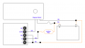
I am currently using a RF control DC switch like this https://www.amazon.com/dp/B098WGK35L?ref=ppx_yo2ov_dt_b_fed_asin_title&th=1

I am wanting to connect it to a constant 12v car battery but because the current draw is 160 mA, it is too high and risk draining the battery too quickly. So my question is, is there a way to control the current draw until I use the remote to activate the switch?

It is currently wired up to actuators and I need some constant power to keep the actuators positioning. Otherwise if I cut all the power, the actuators will do a re-initialization every time before you can control them and that's not what I want here.
 

MrChips

Joined Oct 2, 2009
34,628
If your receiver is drawing 160 mA when idle then something is wrong.
The receiver should be drawing less than 10 mA when idle and less than 50 mA when activated.
 

Thread Starter

dox777

Joined Dec 8, 2024
19
If your receiver is drawing 160 mA when idle then something is wrong.
The receiver should be drawing less than 10 mA when idle and less than 50 mA when activated.
Hmmm, then I am not sure what is wrong. It is currently wired to normally open. When the remote relay is "on", the draw is 71 mA and when remote relay is "off", the draw is 160 mA. Note that this is with actuators connected. Without actuators, the draw is 35 mA when "on" and 3 mA when "off".
 
Last edited:

LesJones

Joined Jan 8, 2017
4,511
I think it is the actuators that are drawing most of the 160 mA not the remote recever unit. It looks lik the receiver elactronics is drawing 3 mA . When it is in the on state it is the relay coils that are drawing 32 mA. Post the schematic of how you have wred the relay receiver to the actuators and abttery showin where you are measuring the current. I think you are measuring the TOTAL current taken by the actuators and the relay receiver. (So the receiver is taking 35 mA when it's relays are actuated and the actuators are taking 125 mA to make the total current 160 mA.) Post thr datasheet for the actuators.
Les.
 

Thread Starter

dox777

Joined Dec 8, 2024
19
I think it is the actuators that are drawing most of the 160 mA not the remote recever unit. It looks lik the receiver elactronics is drawing 3 mA . When it is in the on state it is the relay coils that are drawing 32 mA. Post the schematic of how you have wred the relay receiver to the actuators and abttery showin where you are measuring the current. I think you are measuring the TOTAL current taken by the actuators and the relay receiver. (So the receiver is taking 35 mA when it's relays are actuated and the actuators are taking 125 mA to make the total current 160 mA.) Post thr datasheet for the actuators.
Les.
Yes what you said is correct. I am measuring the total. The measurement is given to me by the bench power supply. I also confirmed this with the multimeter tested in series. I don't have the schematics for the actuators unfortunately and I can't seem to find it. But I have attached the wiring diagram below courtesy of Mr Tonyr1084. I also attached an image of measurements but note in the photo only two actuators are attached and thus it's lower mA. Usually there are 3 that are attached to make the 160 mA.
 

Attachments

Tonyr1084

Joined Sep 24, 2015
9,744
This was one of the things I was concerned with on your other thread. Remember this drawing?
Screenshot 2024-12-26 at 7.08.21 AM.png
The flapper motor can't draw any current unless the key is on. The concern with this was that whatever position the flapper was in when you shut the car off - that would be the position the flapper would be in upon restart.
 

Tonyr1084

Joined Sep 24, 2015
9,744
These are some of the comments from the other thread:
The lighter wires are existing wires of your vehicle. The black wires are the wires you're hooking up. The black dots are connections. Where wires cross each other, without a dot they are NOT connected to one and other.

[edit] I hope this doesn't drain your battery. That's a definite concern, since I don't know how the motor is wired internally. [end edit]
The actuator does not need to be connected to constant power. However, if you're running pipes open when you shut the car off - when you start up again your pipes will still be open. So you don't HAVE to run constant power. In fact, I'm a little concerned that constant power could drain your battery. Like I said before, I have no idea how the internal electronics are wired, or how much power they draw during actuation or in standby. The choice is yours.
 
Last edited:

Tonyr1084

Joined Sep 24, 2015
9,744
Another concern that just now comes to mind, if the motor is constantly drawing power when energized and not moving - it could overheat and shorten the lifespan of the flapper motor. We really don't have enough information on how the flapper works. Perhaps it needs power only when it is being moved from one position to the other. That makes perfect sense to me. Likely to other AAC members as well. It would seem that there is no "Limit Switches" internally that prevent the motor from jamming the flapper full open or full closed.
 

Thread Starter

dox777

Joined Dec 8, 2024
19
This was one of the things I was concerned with on your other thread. Remember this drawing?
View attachment 338970
The flapper motor can't draw any current unless the key is on. The concern with this was that whatever position the flapper was in when you shut the car off - that would be the position the flapper would be in upon restart.
If it worked like this, I would be fine with however it doesn't. The way the actuator works in my case is when you first give it power, it tries to calibrate by scanning the positioning it has to work with by rotating left and right. After it does that once, you can then control it via the relay "on/off" "open/closed" etc. The problem is now when I shut the car off, the actuators no longer gets power, then on the next time I put the car in ACC, the actuators has to do the calibration again which is what I am trying not to do.

So it seems to me, it needs certain current for it to keep its positioning. I am speculating of course as I don't know exactly how it works.
 

MisterBill2

Joined Jan 23, 2018
27,180
I helped with an answer to the other thread on the same topic. It seems that the TS has simply purchased the wrong product for the application. So either get one without that dumb convenience feature or learn to live with it.
The product seems to be another one where adding features turns it into junk.
 

Thread Starter

dox777

Joined Dec 8, 2024
19
I helped with an answer to the other thread on the same topic. It seems that the TS has simply purchased the wrong product for the application. So either get one without that dumb convenience feature or learn to live with it.
The product seems to be another one where adding features turns it into junk.
Yeah I am just more curious as to how it works OEM. I am not using any aftermarket actuators. I am using the same actuators that came with the car. Just using a different controller in which I am trying to mimic the OEM functions.
 

TuriDP096

Joined Feb 3, 2025
3
Hi dox777,
I'm doing a project similar to yours. I bought a Kuster actuator for Audi S3 and I'm trying to do the wiring to use it on another car.
I bought the remote receiver and tried to connect it with the diagram found in the other discussion. I have a few questions for you:


1. When I connect to the power on the bench, the actuator does the calibration but after that it does not open-close. Is it possible that you have to do the calibration on the valve to get the 90 degrees?


2. Have you found a way to put the actuator on stand-by and not lose the calibration?

thanks!
 

Tonyr1084

Joined Sep 24, 2015
9,744
TuriDP096 Welcome to AAC.

We're glad you're doing the necessary research to find the answers you need.

The person who started this thread has not been seen since December 26th 2024. We recommend you start your own thread. You can certainly reference this thread and even link to it. But you're more likely to get answers if you start your own thread. Be prepared to offer as much detail as you can. Schematics, links to parts you have, the vehicle you're working on, possibly some pictures.
 

TuriDP096

Joined Feb 3, 2025
3
TuriDP096 Welcome to AAC.

We're glad you're doing the necessary research to find the answers you need.

The person who started this thread has not been seen since December 26th 2024. We recommend you start your own thread. You can certainly reference this thread and even link to it. But you're more likely to get answers if you start your own thread. Be prepared to offer as much detail as you can. Schematics, links to parts you have, the vehicle you're working on, possibly some pictures.
Thank you Tonyr1084, I will open a new thread!
 
Top