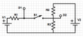
For the circuit shoen with R1=R2=R3=330 Ohms ,V1=V2=5V .What is the volatage at D1 when the switch is closed?Use correct units and give your answer to 2 SF?
And assuming D1 is the voltage after the switch has been closed (i.e., my interpretation of "when the switch is closed"), do you still get the same answer? That is, can D1 be calculated considering R1||R2?
John
"I tried using kvl on V1=R1+R3 to find the I,current"
How can ohms + ohms = volts?
You can of course solve this with KVL or KCL analysis, but I suspect due to the simplicity and the symmetry of the circuit the author is expecting you to reason out a simpler solution, virtually by inspection. You could use superposition for example. Just figure the voltage division of V1 due to R1 in series with R2||R3, then double it since the other source, V2, will produce the same result. Due to the principle of superposition you just add it to the first result -effectively doubling it.
Alternatively, looking at the node D2 it is apparent that the current through R3 must be twice the current through R1 and R2. Since the IR voltage drops must add up to 5V you can easily see what the voltage must be across R3.
In both cases you don't even need to know the resistance values, just that they are all the same.
For the circuit shoen with R1=R2=R3=330 Ohms ,V1=V2=5V .What is the volatage at D1 when the switch is closed?Use correct units and give your answer to 2 SF?
We can't figure out what you are did wrong unless you show us what you did. Having said that, the statement V1=R1+R3 is nonsensical as it equated a voltage to a resistance. Also, when you say that you did it to find the I, you give no indication what I is. Is it the current in the flowing to the right in R1? The current flowing upward in R2? The current in the Euphrates River? You need to clearly define the terms you use.
Wonderful. But I'm assuming that YOU didn't get 3.3 V (otherwise you wouldn't have started this thread). Well, how can we possibly tell why you are getting the wrong answer when you won't show us how you got the answer you did (or even what the answer was that you got)?
BTW: Yes, the correct answer is 3.3 V for the voltage at D2 when the switch is closed.
V3, the voltage across R3, is the result of the voltage division by the network R1 in series with the parallel combination of R2 and R3 from the left hand voltage source. And, additionally, the voltage division of the right hand source via R2 in series with parallel combination of R1 and R3. Since R1=R2=R3, I call each R. Due to the symmetry of the circuit the voltage division of the right hand or left hand source produces the same value, so we just double the result from either case to get V3 (principle of superposition).
so setting up the voltage divider times 2....
V3 = 2 * 5V * [ (R||R) / (R + R||R) ]
now divide the numerator and denominator by R to simplify the calculations.
V3 = 10V * [ (1||1) / (1+1||1) ]
plug in the formula for parallel combinations, 1||1 = (1*1) / (1+1).
 Facebook
 Google
 GitHub
 Linkedin
 110 KB Views: 39


