How to calculate the required filter frequency to remove a certain overshoot

Thread Starter

sindre jacobsen

Joined Apr 1, 2019
40
Hello,

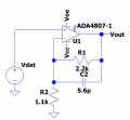
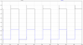
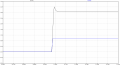
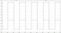
I am trying to apply a step response to an active 1st order low pass filter. When I do, I get quite a bit of overshoot.
Up to now, when I have overshoot, I have just been plugging in different capacitor values to see where the correct filter frequency is that removes the entire overshoot. I feel this is very unprofessional, and I am now wondering if there is a way to calculate the correct filter frequency needed before applying the filter. I have been looking for an answer by searching on google for quite some time now, but have never found an answer to it.

SJ
 

ericgibbs

Joined Jan 29, 2010
18,849
hi sj,
Do you have a diagram of the filter, with values that you could post.?
How are you measuring the overshoot response.?
E
 

SamR

Joined Mar 19, 2019
5,040
Stating the obvious but LTS uses "Perfect" nominally rated devices and capacitors, in particular, can have quite a variance from nominal unless you modify the model. Have you considered using the small variable capacitors to allow some tweaking.
 

Thread Starter

sindre jacobsen

Joined Apr 1, 2019
40
Stating the obvious but LTS uses "Perfect" nominally rated devices and capacitors, in particular, can have quite a variance from nominal unless you modify the model. Have you considered using the small variable capacitors to allow some tweaking.
When you talk about using the small variable capacitors, do you mean by editing the simulation model?
Is there a way to compensate for the overshoot by using the values in the datasheet? Any documents about it or formulas are more than welcome.
Thanks for helping me.

SJ
 

SamR

Joined Mar 19, 2019
5,040
No I assume you were using LTS to model an actual circuit and not getting what you modeled when built. If you are speaking of the output of LTS then no and there are some here well versed in LTS.
 

crutschow

Joined Mar 14, 2008
34,432
You are not seeing overshoot from a 1st-order filter (which does not have overshoot), you are seeing the overshoot from the op amp and stray circuit capacitance response.
That is generally corrected empirically on the actual circuit, since stray capacitance (particularly at the (-) input) has a large effect on the step-input overshoot.
 

Thread Starter

sindre jacobsen

Joined Apr 1, 2019
40
Thanks for all the help.
What I am trying to do is to figure out how much I must slow down the transition of the step response with a filter. I know the Op Amp is the reason for this overshoot, but I am wondering if there is a specific way to calculate the filter compensation required to remove the overshoot due to Op Amp. The simulation is just for showing how the overshoot disappears with a certain filter value, I found this value by plug-and-play, but what I want is to calculate the required filter frequency to remove the overshoot.
 

crutschow

Joined Mar 14, 2008
34,432
I am wondering if there is a specific way to calculate the filter compensation required to remove the overshoot due to Op Amp.
Not exactly.
A significant part of the of the overshoot is due to stray capacitance at the inverting input, not just the op amp, so you would need to know that to do the calculation, and that value depends upon the specific circuit board layout.
 

Thread Starter

sindre jacobsen

Joined Apr 1, 2019
40
Not exactly.
A significant part of the of the overshoot is due to stray capacitance at the inverting input, not just the op amp, so you would need to know that to do the calculation, and that value depends upon the specific circuit board layout.
Do you know of any documents that go into detail on how to calculate and find the different parameters to figure out the appropriate values to remove the overshoot? I want to understand more of how it actually is done, and also actually calculate it.
 

crutschow

Joined Mar 14, 2008
34,432
Do you know of any documents that go into detail on how to calculate and find the different parameters to figure out the appropriate values to remove the overshoot?
Afraid I don't.
Normally that value is determined empirically after the circuit is built, since there are too many unknown variables to accurately calculate the value needed.
 

Thread Starter

sindre jacobsen

Joined Apr 1, 2019
40
Afraid I don't.
Normally that value is determined empirically after the circuit is built, since there are too many unknown variables to accurately calculate the value needed.
Ok, so removing overshoot from a step response is normal to do by means plug-and-play basically? Just want to clarify if that is how it is actually done, or if some approximate calculation is done before fine adjusting due to unknown variables.
 
Top