How to calculate capacitor value for “stepper motor”

MisterBill2

Joined Jan 23, 2018
27,717
The Issue of the Reason for the resistor never really came up!
I believe the OP has received a great deal of information as to attempting running his stepper as an AC synchronous motor.
Rather than attempting to belittle those that have already spent time trying to help the poster, It would probably be better to offer assistance to the OP in his quest for the answer, rather than attempt to assert superiority over those that have already attempted to answer.
Max..
I did offer a fair ammount of good advice, as well as an explanation providing insight as to why the resistor is added.
 

MaxHeadRoom

Joined Jul 18, 2013
30,705
So why the need to belittle the posters that had attempted to answer the OP's questions, but in your opinion, were apparently lacking in offering sufficient information.?
All that was needed was your rebuttal. :rolleyes:
Max.
 

MisterBill2

Joined Jan 23, 2018
27,717
So why the need to belittle the posters that had attempted to answer the OP's questions, but in your opinion, were apparently lacking in offering sufficient information.?
All that was needed was your rebuttal. :rolleyes:
Max.
OK, Max, I was not that hard on anybody, just pointed out that the circuit was wrong.
 

Thread Starter

xchcui

Joined May 12, 2014
309
Have you had any results using @Danko suggested values?
Max,
Danko explanation was really great and informative.
After i was doing some calculations with my old text books,i must say that the several circuit diagrams and the graphes that Danko attached to his answers together with all his other informative(formula,examples,motor mechanical power,links for purchase caps etc)replies were very helpful for my understanding.
So,Danko,thanks alot for your informative and invested replies.

One issue that was not solved yet is regarding to the type of the capacitor.i got two opinions in this thread:
Danko suggested that i can use two polarized capacitor,that will be connected back to back(+--+)to get effect of non-polarized cap.
While,Max said:
You cannot use the electrolytic on AC applications, especially one that requires a deal of current such as this is.
You need high quality AC rated such as ceramic or ideally MKP etc.
Max.
Electrolytic polarized capacitors is cheaper and easier to find as assortment.This is my prefered option,since it is just for 1-2 minute testing.
So,is it okay/safe to use the polarized electrolytes,while they will be connected in that special way(+--+)that will make them act as a non-polar
capacitor?As i said more than once,it is only for testing and i as far as i understand,connecting two electrolyte caps back to back(+--+)is safe opposed to the regular connection.
 

MisterBill2

Joined Jan 23, 2018
27,717
While it is possible to use back-to-back polarized capacitors it is really not a good idea because it does not work the same. Based on the last circuit shown in post #31 from Danko, a parallel set of 5 one microfarad capacitors would come close to the required value, and those capacitors are very commonly available non-polarized types.
In addition, capacitors made for electric motor applications would be suitable, and may be available.
 

MaxHeadRoom

Joined Jul 18, 2013
30,705
Electrolytic polarized capacitors is cheaper and easier to find as assortment.This is my prefered option,since it is just for 1-2 minute testing.
So,is it okay/safe to use the polarized electrolytes,while they will be connected in that special way(+--+)that will make them act as a non-polar
capacitor?As i said more than once,it is only for testing and i as far as i understand,connecting two electrolyte caps back to back(+--+)is safe opposed to the regular connection.
The Bi-polar ones used for regular Induction motor starting, are only placed in circuit for no more than a few seconds, otherwise failure can result.
If using them this way just for momentary testing, monitor them for overheating.
Max.
 

MisterBill2

Joined Jan 23, 2018
27,717
The Bi-polar ones used for regular Induction motor starting, are only placed in circuit for no more than a few seconds, otherwise failure can result.
If using them this way just for momentary testing, monitor them for overheating.
Max.
Motor run capacitors are rated for constant duty and are quite common. Those are the ones I was talking about. And the standard electronics devices up to about 1 mFD, and the very common 0.47 mFD are also rated for fairly constant duty. Check the Grainger catalog, both starting and RUNNING capacitors are available.
 

MaxHeadRoom

Joined Jul 18, 2013
30,705
There are two types of starting capacitors, start only and start/run.
Standard run capacitor do not typically go that high into the μfd range, they consist usually of oil filled paper, rather then the momentary start capacitor, which is typically made of bi-polar electrolytic construction.
Capacitors used and intended for both in Induction motor run mode and AC synchronous stepper motors are made by the likes of CDE etc.
Max.
.
 
Last edited:

Thread Starter

xchcui

Joined May 12, 2014
309
Thanks for your addition information.

I understand why it is better to use the bi-polar capacitors and i tend to choose them,but after some searching it seems that the polarized one are sold in a large assortment and good price,so i will have alot of different value of capacitor for my empirical testing.
If using them this way just for momentary testing, monitor them for overheating.
Max.
If i touch the capacitor with my fingers while it is in operation,what should i feel(heat level)when the capacitor is approaching to be overheating?(The moment that i should disconnect the circuit).
For example,Is the capacitor not considered overheating as long as my finger can withstand the heat of the capacitor?
 

MaxHeadRoom

Joined Jul 18, 2013
30,705
Definitely if discomfort is felt when touching it is near destruction point! :oops:
If you can use values that are in the range of typical motor RUN capacitors, all The Better!
Max.
 

Thread Starter

xchcui

Joined May 12, 2014
309
Okay,Max,i got it,thanks.
I am glad i asked the question here,before i made the circuit
that was shown in youtube,since it turns out that it was
totally wrong(to say the least).
I think that i have now all the tools to solve my issue.
So,thank you very much for everyone help,it was very informative thread
(must say that Danko information was contributed alot to it-especially post#31)and very helpful.All the replies together covered all the aspect for my issue.
Thanks.:)
 
Last edited:

MisterBill2

Joined Jan 23, 2018
27,717
Okay,Max,i got it,thanks.
I am glad i asked the question here,before i made the circuit
that was shown in youtube,since it turns out that it was
totally wrong(to say the least).
I think that i have now all the tools to solve my issue.
So,thank you very much for everyone help,it was very informative thread
(must say that Danko information was contributed alot to it-especially post#31)and very helpful.All the replies together covered all the aspect for my issue.
Thanks.:)
youtube is primarily for entertainment, although there may actually be correct and even useful things once in a while. It is important to keep that in mind.
 

MaxHeadRoom

Joined Jul 18, 2013
30,705
youtube is primarily for entertainment, although there may actually be correct and even useful things once in a while. It is important to keep that in mind.
That does not apply solely to YouTube, ever since the inception of the internet, there have been web pages and other sources set up that float totally wrong information.
Still to this day.
Max.
 

Danko

Joined Nov 22, 2017
2,186
Increase operating frequency of capacitor split phase induction or stepper motor

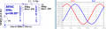
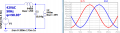
1.8 Degree Hybrid Stepper Motor PN 16298 works from 30VAC, 50Hz.
X_l = R_ser = 0.5 * X_c
Smooth rotation, maximum efficiency:
Capture0.PNG

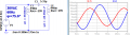
Same motor works from 30VAC, 60Hz.
Big torque vibration and power lost because of coil currents unbalance and improper phase shift:
Capture1.PNG

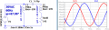
Usually they connect additional resistor in series with capacitor for coil currents equation.
Still has torque vibration and power lost because of improper phase shift:
Capture2.PNG

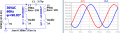
Right way to increase motor operating frequency
X_l = R_ser + Radd = 0.5 * X_c
Smooth rotation, maximum efficiency:
Capture3.PNG

Connecting capacitor in parallel to coil

1. Necessity for use motor with voltage, higher than rated:
X_l = R_ser = X_c
Capture4.PNG

2. Inaccessibility of free leads of coil:
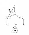
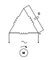
_________Capacitor in series________________Capacitor in parallel_________
1594328741140.png1594328678269.png
 
Last edited:
Top