How to calculate capacitor value for “stepper motor”

Thread Starter

xchcui

Joined May 12, 2014
309
If this is a one time usage just to run the motor, why not do a little empirical testing, until you get it to run smoothly.??
It doesn't sound as though you are putting it into service?
Max.
If the whole set(motor+gear)will works fine,it will go into service.
For an empirical testing you need equipment and electronic component,which i don't have.
 
Last edited:

Thread Starter

xchcui

Joined May 12, 2014
309
Buy these capacitors and experiment with them:
120pcs 50V 15 Values 1uF - 2200uF Electrolytic Capacitor Assortment Tool Set.
$4.99 for set.
Or 120pcs 12 Values 1uF-470uF Assorted Electrolytic Capacitor Assortment Kit Radial.
US $2.45 for set.
View attachment 209341
C1 and C2 should have same value.
Couple C1, C2 works as non-polarized capacitor.
Danko,may you verify your answer according to my question,which was:

"So,the two 100uF(+--+) capacitors will work?
Is it the proven value that i need?
or you just gave a capacitance value for an example?
and that is the reason that you marked them with asterisks? "
 

Danko

Joined Nov 22, 2017
2,186

MaxHeadRoom

Joined Jul 18, 2013
30,706
You cannot use the electrolytic on AC applications, especially one that requires a deal of current such as this is.
You need high quality AC rated such as ceramic or ideally MKP etc.
Max.
 

Thread Starter

xchcui

Joined May 12, 2014
309
It seems that your advices are divided and the thread become to long for this,not complicated,question,while i didn't get the answer that i was looking for.And i still do not agree that the cap value can't be calculate for this simple circuit.
Anyway,thank you all for your advice and help. :)
 

Thread Starter

xchcui

Joined May 12, 2014
309
I already told you, find the inductive reactance of the coil at 50hz/60hz, and calculate the capacitor required to achieve a 90° phase shift.
Max.
How does it help me?
While,i am asking for the formula,you just tell me to make calculation,but without giving me any formula that i be able to do that.
In my case,i know the formula to find the inductive reactance of the coil,which is about 40.82Ω(2*π*Hz*L=Xl).
Now,so i can proceed to the next level,what is the formula to calculate the capacitor required to achieve a 90° phase shift?
 

Thread Starter

xchcui

Joined May 12, 2014
309
Capacitive reactance equal to Inductive reactance equals 90° phase shift.
Max.
As far as i know,this is a resonance situation.
In that case,capacitor with capacitive reactance of 40.82Ω
should be 78uF.
This will cause the phase angle to be zero in the coil+capacitor branch,while between the two branches will be a phase shift of 90°(since voltage leads the current at 90° phase shift on in the coil branch)
Am i right?Does it mean that i need to start empirical testing
with this value-78uF capacitor?
 

Danko

Joined Nov 22, 2017
2,186
As far as i know,this is a resonance situation.
In that case,capacitor with capacitive reactance of 40.82Ω
should be 78uF.
This will cause the phase angle to be zero in the coil+capacitor branch,while between the two branches will be a phase shift of 90°(since voltage leads the current at 90° phase shift on in the coil branch)
Am i right?Does it mean that i need to start empirical testing
with this value-78uF capacitor?
You did not take in account coil resistance, which is connected in series with inductance:
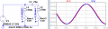
1592131128561.png

Phase shift between currents is 90°, but current in L2 is too small,
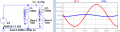
because your motor designed for 500 Hz frequency (X_L = R_ser @500Hz):
1592132352228.png

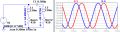
At 500 Hz motor works just fine, because X_L = R_ser = 0.5*X_C (formula you are trying to find):
1592137324415.png
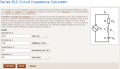
https://www.translatorscafe.com/unit-converter/en-US/calculator/series-rlc-impedance/
1592223264567.png
1592256509504.png
ADDED:
1.8 Degree Hybrid Stepper Motor PN 16298 works from 30VAC, 50Hz:
1592324734497.png
 
Last edited:

Thread Starter

xchcui

Joined May 12, 2014
309
As far as i know,this is a resonance situation.
In that case,capacitor with capacitive reactance of 40.82Ω
should be 78uF.
This will cause the phase angle to be zero in the coil+capacitor branch,while between the two branches will be a phase shift of 90°(since voltage leads the current at 90° phase shift on in the coil branch)
Am i right?Does it mean that i need to start empirical testing
with this value-78uF capacitor?
Max,what is your opinion about my last post(above)?

Danko,i took into account the coil resistance.
78uF capacitor will cause the CL branch to be in resonance,while the resistance on that branch will be the pure resistance of the coil 410Ω.So the the current and voltage in that branch will be the same phase.
At the other branch the voltage will leads the current in ~90° phase shift compare to the second branch and each branch will get 29mA current.I made the calculation accordind to my old school text book.
I don't know how did you get your value.
Something seems to be wrong(as i see it)with the LTspice simulation.I don't trust on this software ,but of course
i may be wrong .
 

Thread Starter

xchcui

Joined May 12, 2014
309
I already told you, find the inductive reactance of the coil at 50hz/60hz, and calculate the capacitor required to achieve a 90° phase shift.
Max.
Capacitive reactance equal to Inductive reactance equals 90° phase shift.
Max.
Max,you gave me some kind of small information how to start the calculations.I used that information(as far as i understand what was your intention)and tried to solve my issue:

As far as i know,this is a resonance situation.
In that case,capacitor with capacitive reactance of 40.82Ω
should be 78uF...
Now,i am waiting for a reply from you so you will tell me if i understood you right or not.May you tell me if this was your intention?
It will be very helpful.
 

MisterBill2

Joined Jan 23, 2018
27,722
For this inductance and R_coil=410 Ω, capacitor should be 60 uF,
then phase shift is 90°, but currents in coils are too different:
View attachment 209041
This problem solved in more complicated circuit:
(Because coils are connected in series, voltage source is 24 VAC, 50 Hz)
View attachment 209045
You can simulate circuits yourself in free LTspice software:
DOWNLOAD LTspice

ADDED:

Capacitors must be non-polarized.

Easy. It is possible, if R_L=X_L or R_L<X_L.
For stepper motor or split phase induction motor:
R_L=X_L (if R_L<X_L, then connect additional resistor in series with C);
X_C=2*X_L (if C connected in series with L);
X_C=X_L (if C connected in parallel to L).
REACTANCE CALCULATOR

@xchcui, below is highly recommended by @MaxHeadRoom
"looks right, compared to the SloSyn" circuit, where 0.75 uF capacitor
provided accurate 90° phase shift.
View attachment 209620
You may not use R1 at all, because any resistance decreases current of L2.
ONLY the second circuit shown in post #14 shows a circuit like the one used with the Slo-Syn motors. The resistor and capacitor IN SERIES with the second phase coil.
So a capacitor IN SERIES with one of the phases of a stepper motor is what is required.
To calculate the value of the series capacitor one will need to know the inductance of the winding it is in series with, and then the value to provide a 90 degree phase shift can be determined. Since that value will be very close to resonating with the coil at the supply frequency, a series resistor will be required to limit the current to close to the current through the directly powered coil.
I am amazed that none of the other experts were aware of the purpose of the resistor. For very short duty cycles the resistor is sometimes reduced or left out to provide greater torque.
 

MisterBill2

Joined Jan 23, 2018
27,722
I'm amazed you put yourself in that category.
Well, Mister Shortbus, just consider that all of the other remarks were considering a capacitor ACROSS the motor winding, which is seriously incorrect. THAT is why my remark about "experts". The fact is that I have done quite a few machines using SloSyn motors and a whole lot of machines using stepper motors. Thus I am indeed rather familiar with their circuits.
 

MaxHeadRoom

Joined Jul 18, 2013
30,706
a capacitor ACROSS the motor winding, which is seriously incorrect.THAT is why my remark about "experts".
Stated right off the bat in post #2, ;)
I have used my SloSyn "Design Engineers Guide to AC Synchronous and DC Stepping Motors" circa 1976, as a reference for some decades now.:cool:
Still Pertinent!
Max.
 
Last edited:

MaxHeadRoom

Joined Jul 18, 2013
30,706
I am amazed that none of the other experts were aware of the purpose of the resistor.
The Issue of the Reason for the resistor never really came up!
I believe the OP has received a great deal of information as to attempting running his stepper as an AC synchronous motor.
Rather than attempting to belittle those that have already spent time trying to help the poster, It would probably be better to offer assistance to the OP in his quest for the answer, rather than attempt to assert superiority over those that have already attempted to answer.
Max..
 
Last edited:
Top