That "get rid of everything that we don't need" instinct comes from me having built a few battery powered projects recently, which were designed to last years.
I also believe in that.
I design a circuit and then look at it for some time to see if there's anyway to simplify it.
I like the adage attributed to Einstein: "Make it as simple as possible, but no simpler."
I dont get it. When power is left on, Q2 is on and thus drawing current. How is this more efficient then crutschow's circuit which basically just discharge the cap via the diode... 560k vs 100k
Late to the party, I'm not a big fan of loooong R-C timers. Here is an alternate reality.
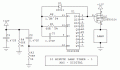
When 12 V power is applied, R3-C2 resets the CD4060 counter, driving the Q14 output low and turning on transistor Q1. After 8192 oscillator cycles, Q14 goes high. This turns off the lamp and stops the oscillator through D1. The circuit sits frozen until power is removed. R4 discharges both the decoupling capacitor C3 and the reset capacitor C2 in under 1 second.
With the oscillator values shown, things calculate out to about 9.6 minutes. R1 and C1 set the oscillator frequency; the equation is on the datasheet.
None of the components have critical values. R3, R4, C2, and C3 can be any of a wide range of values, The ones shown were chosen because they already are used somewhere else. Q1 can be any p-channel power MOSFET rated for twice the voltage and current of the lamp. Or it can be changed to a PNP bipolar transistor with an appropriate base current limiting resistor.
If the lamp must be connected to the 12 V source and switched to GND, let me know and I'll add an inverting stage.
I'm looking at a case where the battery was turned on, the lights went off for 10 minutes and then forgot to turn the battery off. Then your 1k" resistor will consume 12mA. It will also consume a timer. I replaced the timer with a low CMOS timer and I have a 100k" resistor. Discharges the capacitor transistor immediately after the battery is disconnected. And the power supply of the circuit in this standby mode can last several days.
Late to the party, I'm not a big fan of loooong R-C timers. Here is an alternate reality.
When 12 V power is applied, R3-C2 resets the CD4060 counter, driving the Q14 output low and turning on transistor Q1. After 8192 oscillator cycles, Q14 goes high. This turns off the lamp and stops the oscillator through D1. The circuit sits frozen until power is removed. R4 discharges both the decoupling capacitor C3 and the reset capacitor C2 in under 1 second.
With the oscillator values shown, things calculate out to about 9.6 minutes. R1 and C1 set the oscillator frequency; the equation is on the datasheet.
None of the components have critical values. R3, R4, C2, and C3 can be any of a wide range of values, The ones shown were chosen because they already are used somewhere else. Q1 can be any p-channel power MOSFET rated for twice the voltage and current of the lamp. Or it can be changed to a PNP bipolar transistor with an appropriate base current limiting resistor.
If the lamp must be connected to the 12 V source and switched to GND, let me know and I'll add an inverting stage.
I know that a lamp is essentially a resistive load. But, wouldn't it be good practice to place an inverse parallel diode across it? Say someone took out the lamp while it was still on ... wouldn't Q1 go kapoot?
Yes, an inductive kick in a 12 V circuit easily could puncture a 55 V device. But ...
Note the zener diode built into the MOSFET decal. That is a real thing, a consequence of the fabrication process. It prevents overvoltage of both polarities. The zener voltage is rated just above the device max. Vds. In the other polarity it acts as a power diode with a Vf of 1 V or so.
Actually I am planning on putting an XL6009* DC-DC Boost converter there and then some 24 volt LED strips, so I think it doesn't really matter which way it gets switched on.
And thank you for the different approach, it is always good to see more solutions for the same problem, even if only for the sake of learning to think in different ways.
*I have quite a few DC-DC converters laying around, that was just the one I remembered first
And also I am using a variable boost converter to be able to regulate the brightness if necessary
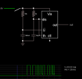
The resistor is needed to rapidly discharge C1 when the power is turned off prior to the timeout.
It could be a larger resistor if you can tolerate a longer reset time for that situation.
Obviously you can't connect that point to ground.
Silly me.
I forgot about the 1kΩ resistor.
That could be a problem if the circuit is battery powered.
The resistor is needed to rapidly discharge C1 when the power is turned off prior to the timeout.
It could be a larger resistor if you can tolerate a longer reset time for that situation.
Obviously you can't connect that point to ground.
I swapped it out for a larger one, because I didn't need that fast of a reset time.
The circuit is powered by a car battery, so I guess, that those few mAs don't really matter for a battery that big.
And I did not mention that the circuit was battery powered, because I felt like I could do away with any parts that for some reason consumed too much power.
The 10 minute power off is more of a failsafe, and compared to the Amps that the LEDs will end up drawing, R1 draws less than 1/1000th of that (in my current configuration) so it is really negligible.
The reason the circuit in post #26 resets in a few milliseconds without a low-value resistor is that the timing capacitor does not have to be discharged to assure the accuracy of the next timing cycle. That, and the R-C time constant is 17,000 times smaller than in the 555 circuits.

 Facebook
 Google
 GitHub
 Linkedin