How to add these LED together ? Please help !!!

Thread Starter

Le7316

Joined Aug 29, 2015
4
Hello All ,

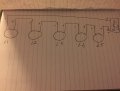
Long story short , I have ten lights in the photos below and each of the light contains two LED in there as you can see from the photos . Now I'm assuming the resistors are already built in and the question now is how do I bundle ( connect ) 5 lights together so that I have two different set of light . Am I going to connect each lights in series ? I know you guys are going to ask for the specifications but unfortunately this is what the seller told me , and oh this is an automotive project meaning it will be 12V .image.jpgimage.jpgimage.jpgimage.jpg


Specifications:

Light source: LED
Wattage: 9W
Material Type: Aluminium alloy + LED
Voltage: 12V
Color Temperature: 6000-7000 K
Special Features: Waterproof, stealth
Item type: Daytime Running Lights
Item Diameter: 1.8 cm
Item Weight: 50g
Connector Type: Plus-n-Minus lunk
Luminous Flux: 120 lm
 

Hypatia's Protege

Joined Mar 1, 2015
3,228
Am I going to connect each lights in series ?
and oh this is an automotive project meaning it will be 12V .
The above statements are inconsistent:confused: Unless, that is, you are contemplating incorporation of power conversion circuitry - though I see no rationale for such a scheme?

how do I bundle ( connect ) 5 lights together
each of the light contains two LED
Assuming the specifications are 'per unit' (as opposed to 'per LED'):
I suggest you connect them in parallel then power them from an appropriately (over-current) protected line --- Based upon the provided specifications, each 'bundle' will draw up to Ca. 4A

Should the specifications be 'Per LED'
Ditto -- except the current requirement will be Ca. 8A each bundle...

NOTE: If the specs are 'Per LED' and the 'lamps' are comprised of two series connected LEDs then they are inapplicable to 12V operation sans modification --- By way of avoidance of confusion; this note does not apply if you are certain the 'lamps' operate properly on 12V...

In either case, please bear in mind that "12V" automotive electrical systems may produce up to 15V -- Depending upon the LEDs maximum specifications a 'voltage' regulator or current limiting scheme may be required.

Best regards
HP:)
 
Last edited:

Alec_t

Joined Sep 17, 2013
14,263
Welcome to AAC!
Bear in mind that modifying the lighting arrangement on a vehicle will probably invalidate your insurance (check with your insurer) and will have to be done so as to comply with Vehicle Lighting Reulations applicable where you live.
 

Thread Starter

Le7316

Joined Aug 29, 2015
4
Thank you for all the replies and let's just called this Unit 1,2 to 10 and what I want to do is connect the first five units ( see attached ) as a group 1 . Am I going to damage those LED if I'm connecting like that ? The whole purpose of doing this is to reduce the number of wires ..like supposed to have 5 negatives and 5 positives and now you only have one negative and one positive and then connect them to the power source . Thoughts ?
 

Attachments

Thread Starter

Le7316

Joined Aug 29, 2015
4
Understand your concerns but is there a way to connect 5 units together to reduce the number of wires down to one pos and one neg ?

Thanks !!
 

Hypatia's Protege

Joined Mar 1, 2015
3,228
Understand your concerns but is there a way to connect 5 units together to reduce the number of wires down to one pos and one neg ?

Thanks !!
I apologize that I don't understand your difficulty?:confused: -- Having paralleled the devices you'll have one positive terminal and one negative terminal formed of a junction of five leads each... --- If you wish to arrange the LEDs as a 'string' you need merely connect same 'ladder fashion' to a pair of (positive and negative) leads running the desired course...

In any event, please don't neglect incorporation of over-current protection -- and consideration of the +15V (maximum) system EMF...

Best regards
HP:)
 
Last edited:

Thread Starter

Le7316

Joined Aug 29, 2015
4
If you wish to arrange the LEDs as a 'string' you need merely connect same 'ladder fashion' to a pair of (positive and negative) leads running the desired course...

In any event, please don't neglect incorporation of over-current protection -- and consideration of the +15V (maximum) system EMF...

HP,

Thank you for ur explanations but I'm not quite sure what you mean by the last two sentence ........Maybe a diagram or drawings would help?

Thanks !!!
 

Hypatia's Protege

Joined Mar 1, 2015
3,228
Maybe a diagram or drawings would help?
Note: In the diagram (below) the LED symbols represent entire 'lamp units' as described in your OP.

LedLadder.jpg

Thank you for ur explanations but I'm not quite sure what you mean by the last two sentence
It is imperative that you implement over-current protection (e.g. appropriate fuses, breakers, etc...) --- If the LEDs will not withstand continuous operation at 15V (or the current/power attendant to such operation) you are strongly advised to implement a 'Voltage' regulation and/or current limiting scheme...

Best regards
HP
 
Top