 Facebook
 Google
 GitHub
 Linkedin
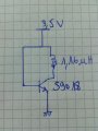
i have this circuit that oscillate around 104Mhz ..
i want to know how does it oscillate
and how i can calculate the frequency
i want to know how does it oscillate
and how i can calculate the frequency
Attachments
-
 175.2 KB Views: 30


