How the 3 stage multivibrator (ring oscillator) works?

Thread Starter

gmerab2003

Joined May 2, 2025
7
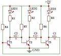
Here below are elements and their numeric values of 3 stage multivibrator (ring oscillator) and how they are connected.
VCC=+5V
VCC → LED3 → R3→ T3 collector & Left plate of C1
VCC → R6 → T3 base & Right plate of C3
VCC → LED2 → R2→ T2 collector & Left plate of C3
VCC → R5 → T2 base & Right plate of C2
VCC → LED1 → R1→ T1 collector & Left plate of C2
VCC → R4 → T1 base & Right plate of C1
T1, T2 and T3 Transistor emitters are connected to ground
Transistors: T1, T2, T3 (assumed to be NPN BJTs),
Resistors: R1= R2 = R3 = 33Ω, R4 = R5 = R6 = 33kΩ,
Electrolytic capacitors: C1 = C2 = C3 = 47µF
 

Attachments

Thread Starter

gmerab2003

Joined May 2, 2025
7
Hello ericgibbs, I have read very nice explanation of Multivibrator i.e. how and when capacitos are charging and discharging, when transistors are open or closed. I'd like to get the same explanation for this scheme, because a little is inclear for me how the transistors are opened in sequence. Would you please to help in such case?

,
 

meth

Joined May 21, 2016
298
A picture is worth 1000 words, a video maybe even more.
If you search for animation how multivibrators work, I think that would help you the most... to see what conducts when, when it stops and what is charging.. how the votlages change..
Here is the first that I found helpful but if you search for videos/animations it would be very more easy for you to understand than written words:


Thread Starter

gmerab2003

Joined May 2, 2025
7
Thanks meth, I have read very briliant explanation byJony130 on "Astable Multivibrator - How does it work?" and everything is clear now for me, but on 3 stage multivibrator i.e. ring oscillator is not easy to understand how this scheme works, because there is a additional one transistor totally 3 transistors and how and when they are opening it's not very clear one. Would you please to give me recomendations where to find the information on 3 stage multivibrator work?
 

kami100

Joined Apr 30, 2025
6
Clock frequency the fundamental frequency pulse from which other time-based signals derive of a digital clock can be generated employing a 3-stage multivibrator also referred to as a ring oscillator. It is created by connecting three inverters (NOT gates)** in a loop, meaning the output of one is connected to the input of the next one, while the output of the last is fed into the first.

Simplistic breakdown of its operation:

Step 1. Each inverter modifies the signal and outputs the inverse. A high signals turns into a logic low and vice versa.

Step 2. The output from other inverters feeds back to the previous step. In this case, signal stabilization is impossible because with three inverters, the signal being outputted keeps oscillating.

Step 3. When the signal is implemented, oscillation ensues. When each inverter adds slight delays, it takes time for the signal to propagate through the loop. This delay along with the oscillation causes a continuous cycle of changes, establishing a square wave signal.

Walkthrough example:

The input of the first inverter is set to logic 1.

First inverter quotes: output is 0 →second inverter receives 0→ outputs 1→third inverter receives 1→ outputs 0 which then cycles back to the first inverter.

First inverter sees 0: outputs 1 again and allows the loop to perpetuate.

Important points:

Ring oscillators get their name because the outputs have feedbacks that are looped in a ring.

To maintain oscillating behavior, an imbalanced quantity of inverters is needed. An even amount would eliminate the inversion effect and settle at a stable point.

The frequency relies on the quantity of stages and the delay of each gate.

Applications:

Ring oscillators are applied in:

The generation of clocks

Generating numbers at random

Testing the effectiveness of semiconductor devices

Semiconductor performance testing
 

Thread Starter

gmerab2003

Joined May 2, 2025
7
kami100
Your ideas are interesting, of course, but I am mainly interested in the fact that when, for example, the first transistor turns on, it of course turns off the second transistor, but why should the third transistor turn off and can it also turn on together with the first transistor? In general, I am interested in what order the transistors will open: the first, second and third, and why? Or if one of them does not open, then why?
 

sparky 1

Joined Nov 3, 2018
1,218
Possibly build a mutivibrator in ltspice, it should use a transistor model. The working multivibrator simulation should be saved in case you need to revert.
Change the name to a new name and add 2 more stages forming a loop.

There is a mosfet ltspice ring oscillator on github. I thought it is very well organized and illustrated looking briefly at the readme file.
There are several other ring oscillators, amazing progress, one looks like the pcb might have shared project availability.
CMOS_Ring_Oscillator/circuits at main · swastim01/CMOS_Ring_Oscillator · GitHub

The ring oscillator as a discrete NPN project? On the CMOS ring I often wondered how many useful harmonics
there where and if the temperature would climb and settle differently from a 60 degree RC phase shift oscillator?
It might be a fun thread.
 
Last edited:

Jony130

Joined Feb 17, 2009
5,593
Can you explain what prevents you from understanding how this circuit works? Because it works the same as a classic two-transistor astable multivibrator.
 
Last edited:

Thread Starter

gmerab2003

Joined May 2, 2025
7
Hello Jony130, Excuse me for late answer:
I have read your very briliant explanation on "Astable Multivibrator - How does it work?" and everything is clear now for me, but on 3 stage multivibrator i.e. ring oscillator is not easy to understand how this scheme works, because I can understand that when
T1 transistor is opened, it will close T2 transistor via C2 capacitor, because minus voltage is going to T2' base and it will be closed, but what prevents T3 transistor in such situation not to be opened also together with T1?
 

panic mode

Joined Oct 10, 2011
4,864
if you want to understand something - study it. build circuit or use simulator. and then if something does not make sense, ask for help and supply data. i am still not sure what you mean by "opened" and "closed"...

each stage has own propagation time determined by RC values. when transistor is off (not conducting), Vce is high. when transistor is on (conducting), Vce is low and LED is lit. in this image Vce of the three transistors are shown as three graphs on the bottom. if we mark the pulses as three phases (1/2/3), then you will notice that at any time two transistors are on (and two LEDs are lit). the graphs on top are currents through R1/R2/R3 and respective transistor (T1/T2/T3). when the any of the currents is on, LED for that channel is on (not shown in simulation).

1746830058920.png
 

panic mode

Joined Oct 10, 2011
4,864
to put it simply, if there is enough of time and there is no transient from previous stage, then transistor in each stage would turn on... and stay on... because base is connected to supply voltage by resistor. that is the stable (default) state that each stage is trying to achieve (and all LEDs would be on).

the only thing preventing this peaceful steady state is that there IS a transient that comes from previous stage (through capacitor). this temporarily turns off this stage... so what you see as pulses in lower three graphs (voltages Vce of each transistor) is actual OFF state for that transistor. this is what propagates round and round...

you can increase number of stages to 4,5,6,7... you will not get additional phases but... they will not look nice since not decoded. it may look like lights chases in both directions.
 
Last edited:

Thread Starter

gmerab2003

Joined May 2, 2025
7
A picture is worth 1000 words, a video maybe even more.
If you search for animation how multivibrators work, I think that would help you the most... to see what conducts when, when it stops and what is charging.. how the votlages change..
Here is the first that I found helpful but if you search for videos/animations it would be very more easy for you to understand than written words:

Thanks a lot, it's very useful video
 

Thread Starter

gmerab2003

Joined May 2, 2025
7
if you want to understand something - study it. build circuit or use simulator. and then if something does not make sense, ask for help and supply data. i am still not sure what you mean by "opened" and "closed"...

each stage has own propagation time determined by RC values. when transistor is off (not conducting), Vce is high. when transistor is on (conducting), Vce is low and LED is lit. in this image Vce of the three transistors are shown as three graphs on the bottom. if we mark the pulses as three phases (1/2/3), then you will notice that at any time two transistors are on (and two LEDs are lit). the graphs on top are currents through R1/R2/R3 and respective transistor (T1/T2/T3). when the any of the currents is on, LED for that channel is on (not shown in simulation).

View attachment 348839
From your post I can see that when Q1 transistor is on (conducting) then it forces Q2 transistor to be off (not conducting), but Q3 transistor at the same time is also on? That is the same question which I was asking in my previous post
 
Top