How has this been done?

Thread Starter

The_Apprentice_

Joined Oct 3, 2019
9
Can anyone help or point me in the right direction. I'm very new to circuit design and would like some assistance/guidance.
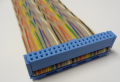
I work a lot with ribbon cables & I wanted to create a device that would check the continuity of the ribbon cable from end to end.
I came across this video and would love to know how this was achieved and what steps I can take to create my own one.

Any help would be greatly appreciated, thanks.
 

MaxHeadRoom

Joined Jul 18, 2013
28,617
Just a apply a voltage via P.B. voltage to all odd numbers on the bottom row, and connect a LED to each of the odd numbers on the top connector, do the same for the even numbers pins with a button and separate LED's. for the even numbers.
Max.
 

Thread Starter

The_Apprentice_

Joined Oct 3, 2019
9
Just a apply a voltage via P.B. voltage to all odd numbers on the bottom row, and connect a LED to each of the odd numbers on the top connector, do the same for the even numbers pins with a button and separate LED's. for the even numbers.
Max.
I'm really sorry but I'm not fully sure I understand.
So I apply a voltage to the P.C.B & have a volatage going to all odd numbers and apply an led for each odd number. Then I also have a switch that switches the power to the even numbers and another set of Leds designated for them.
Then if there was a short for e.g. between pin 6 & 7. When I supply power to my even numbers my led for pin 7 will come on as well showing I have a short?
Is this correct?
Thanks
 

crutschow

Joined Mar 14, 2008
34,281
I came across this video and would love to know how this was achieved and what steps I can take to create my own one.
That appears to be a very simple circuit that has 1 LED (plus current limit resistor) in series with each wire from a voltage source (which could be a battery).
Typically you only need a few mA through a high-brightness LED for it to be readily visible.
The needed voltage and resistor value depend upon the color LED you want to use.
 

crutschow

Joined Mar 14, 2008
34,281
Then if there was a short for e.g. between pin 6 & 7. When I supply power to my even numbers my led for pin 7 will come on as well showing I have a short?
Is this correct?
Yes, it tests both for continuity and for shorts between odd and even pins.
But if you have a short, all the LEDs will illuminate since you would now be providing power to both sets of pins.

If you want to know which pins are shorted you could put a diode in series from the supply to each pin.
Then only the shorted pin will light on the opposite row.
 
Last edited:

MaxHeadRoom

Joined Jul 18, 2013
28,617
Although presumably even if just only one pin is shorted (or open) it means the whole connector may have to be re-connected.
Max.
 
Last edited:

MrSoftware

Joined Oct 29, 2013
2,188
I don't think you want all wires to be powered at the same time. If something is mis-wired or shorted, the LEDs may still light up. I have a similar wire tester for testing wire harnesses (not ribbon cables) and occasionally the assemblers get their wires crossed up, but all the LEDs on the tester still turn on so the problem goes unnoticed. Instead I think you want it to walk down the line, powering one wire at a time and using the adjacent wire for return. Similar to how CAT5 cable testers like this one work (jump to about 1:30). This way each wire is powered individually and you have much better odds of catching a problem.
 

AlbertHall

Joined Jun 4, 2014
12,345
How about connecting say 1k resistors across the pins so that they are all in series and then measuring the total resistance?
Opens will give open circuit reading, shorts and crossed wires will give a lower than expected resistance. It doesn't tell you where the fault is but gives a very quick go/no go test.
 

MrSoftware

Joined Oct 29, 2013
2,188
That's not likely to occur with ribbon cables.
It is possible for someone to put one plug on backwards. Also I don't know about his specific case, but not all ribbon cables are plain jane ribbon cables, and going one light at a time would tell you which pin on side A matches which pin on side B. Here are some examples where the pins are different and/or it would be easy to mix things up if manually making the cables:

upload_2019-10-3_19-43-2.png

upload_2019-10-3_19-44-45.png

upload_2019-10-3_19-40-25.png
 

Attachments

crutschow

Joined Mar 14, 2008
34,281
Here are some examples where the pins are different and/or it would be easy to mix things up if manually making the cables
For those cases I agree they could get mixed up, but not so likely for a flat ribbon cable with 1:1 connections.
Would have to decide if checking for that is worth the large amount of added logic and circuit required to check each connection individually.
 

Thread Starter

The_Apprentice_

Joined Oct 3, 2019
9
Yes, it tests both for continuity and for shorts between odd and even pins.
But if you have a short, all the LEDs will illuminate since you would now be providing power to both sets of pins.

If you want to know which pins are shorted you could put a diode in series from the supply to each pin.
Then only the shorted pin will light on the opposite row.
So a simple circuit like this would do the job?
https://ibb.co/QNS8bVt
 
Last edited:
Top