hi 193,
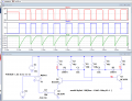
Now that you have handed in your assignment, this LTS simulation shows your Astable working. OK. 11kHz.
As one poster suggested that both transistors turning On at the same, is wrong,
Also suggesting shorting out the diodes is a bad idea, as it puts a -11V level on the transistor Bases, the diodes limit voltage to approx -6V.
As someone suggested the 12V power could be switch ON to start the Astable, but switching the Astable On using the 12V rail would not ensure the Q1C and Q2C states always start in the same Phase...
I see that the frequency of the oscillator is higher with the diodes then the capacitors do not have enough time to charge to a voltage as high as without the diodes. Then only some transistors will be destroyed by the emitter-base avalanche breakdown because the breakdown voltage is a range of voltages from 5V or 6V to maybe 9V.
Then only some transistors will be destroyed by the emitter-base avalanche breakdown because the breakdown voltage is a range of voltages from 5V or 6V to maybe 9V.
hi agu,
I think you will agree that the circuit works as posted by the TS.
It will most likely damage the BE of the transistors if the diodes are linked out.
Usually you are more precise in your answers, just saying Then only some transistors will be destroyed or breakdown voltage is a range of voltages from 5V or 6V to maybe 9V, will just confuse the TS.
My very first job was with Philips and an engineer showed me the datasheet for the same very old transistor as is used in this school project, the BC107. The engineer showed me the Absolute Maximum Veb voltage breakdown rating of 6V and said to Never Ever exceed it. Then I Never Ever exceeded Absolute Maximum ratings on anything I designed.
The teacher did not provide a schematic of a simple multivibrator without the diodes and powered from a safe 5V.
 Facebook
 Google
 GitHub
 Linkedin
")