It's my final project. I need to provide information of its working briefly and its equations. I'm seeing similarity to astable multi vibrator but I can't say how it works. Your help is appreciated
No idea. I don't know why is that switch there. I have the proteus simulation file for it, want me to put it here?
Its got an error though, I get zero output signal of it and I don't know why.
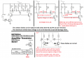
It is a very simple multivibrator but its diodes are in the wrong places.
A real circuit has noise that starts it. A simulator has no noise so you must add a startup pulse to get it oscillating.
It's my final project. I need to provide information of its working briefly and its equations. I'm seeing similarity to astable multi vibrator but I can't say how it works. Your help is appreciated
The teacher will give me extra points for pointing out the circuit errors.
The student's simulation probably has both multivibrator transistors turning on at the same time instead of alternating.
It's my final project. I need to provide information of its working briefly and its equations. I'm seeing similarity to astable multi vibrator but I can't say how it works. Your help is appreciated
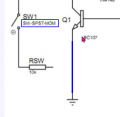
Of course the circuit will not work if the switch does not turn on Q3 or if Q3 is not replaced with a wire.
Why doesn't the switch simply turn on the power supply +12V to the circuit instead of using Q3?
I showed and the first article posted by Bertus showed correct positions for the diodes so that the transistors are not destroyed by too high emitter-base voltage. The datasheets say Absolute Maximum Veb= 5V or 6V.
Of course the circuit will not work if the switch does not turn on Q3 or if Q3 is not replaced with a wire.
Why doesn't the switch simply turn on the power supply +12V to the circuit instead of using Q3?
hi agu,
It is a circuit configuration that intended to make the student have to figure out what are the function of the individual components have in the circuit, it is not necessarily a practical design.
As the other member have already mentioned it won't work because the current path won't be provided for Q1. Yet, why Q3 and not a short circuit to ground?
I understand that you are trying to make me figure this out by giving hints instead of giving answers but I'd appreciate providing answer as tomorrow is the last day to deadline.
 Facebook
 Google
 GitHub
 Linkedin

")