 Facebook
 Google
 GitHub
 Linkedin
Hi,
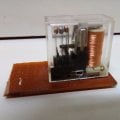
I've noticed that in a DC relay the electromagnetic coil is just an electromagnet with a large no of turns as shown in below pic.
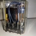
But when I examined the AC relay I've it just has a thick piece of copper in a the black circular cylinder, with no visible coil turns. So, does the AC relay has any coils like in a DC relay or just one thick central copper electrode.
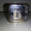
Also I've a doubt relating to the relay shown in below 120VAC relay in the pic.The details on the top of the relay are given below:
Furnas
46PB33A01
Industrial rated
3A, 1/2HP, 600VAC
10A, 1/3HP, 120VAC
6 2/3A, 1/3HP, 250VAC
Appliance rated
10A, 250VAC
Made in Mexico
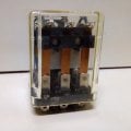
Since, the relay has three group of conductors for COM,NC and NO it seems to be a 3-phase relay. So does it mean @ 120VAC each conductor handles 10A or all the 3 conductors together handle 10A?
I've noticed that in a DC relay the electromagnetic coil is just an electromagnet with a large no of turns as shown in below pic.
But when I examined the AC relay I've it just has a thick piece of copper in a the black circular cylinder, with no visible coil turns. So, does the AC relay has any coils like in a DC relay or just one thick central copper electrode.
Also I've a doubt relating to the relay shown in below 120VAC relay in the pic.The details on the top of the relay are given below:
Furnas
46PB33A01
Industrial rated
3A, 1/2HP, 600VAC
10A, 1/3HP, 120VAC
6 2/3A, 1/3HP, 250VAC
Appliance rated
10A, 250VAC
Made in Mexico
Since, the relay has three group of conductors for COM,NC and NO it seems to be a 3-phase relay. So does it mean @ 120VAC each conductor handles 10A or all the 3 conductors together handle 10A?
Attachments
-
 35.6 KB Views: 27
 -
 52.9 KB Views: 26
 -
 40.1 KB Views: 26
 -
 66.4 KB Views: 25


