How does my oscillator circuit work?

Thread Starter

kasperzacho

Joined Nov 2, 2017
9
Hello

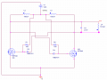
I have constructed the following oscillating circuit found in the attached pictures.


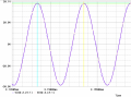
I have tested the circuit and it works. Giving out a sinusodial wave across the coil "L4" with the corrects resonance frequency given by C3 and L4.
however I do not fully understand how the gate-source voltage and drain-soruce voltage work in this setup.

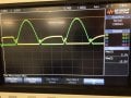
I have also attached a picture of the gate-source and the drain-source of one of the n channel MOSFETs with a VDC set to 5V! not 12V in this case.


Can someone tell me why the voltages behave like this? What makes the system oscillate like this?

Thanks for your inputs and feel free to ask for more information if you need it!
 

Attachments

Dodgydave

Joined Jun 22, 2012
11,285
It's a classic two transistor multvibrator, self oscillating pushpull type, one transistor turns on first, and pulls the other's gate supply off for a brief second, then the other transistor turns on and the cycle repeats. Usually it uses a centre tapped transformer.
 

Thread Starter

kasperzacho

Joined Nov 2, 2017
9
It's a classic two transistor multvibrator, self oscillating pushpull type, one transistor turns on first, and pulls the other's gate supply off for a brief second, then the other transistor turns on and the cycle repeats. Usually it uses a centre tapped transformer.
Thank you that helped a lot. Would you happen to know how to find an expression for the voltage across the inductor L4?
 

MrAl

Joined Jun 17, 2014
11,389
Hi,

This kind of circuit is not easy to analyze mathematically because of the mutual inductances. This is where a simulator really works better.
You can probably get an idea what causes the frequency of oscillation by computing the LC network and think of the two 150uH inductors as creating an ideal transformer. That gets you a little information at least.
The LC network on the output will go through part of it's normal cycle naturally and that will change the state of the transistors.

We might find out more by looking at a simulation in various places. That's about the best way to handle this otherwise you will have to look into how to handle mutual inductance when there are three inductances involved, which is much more difficult than when only two are involved. We might also find shortcuts to a math analysis by observing the various responses at the different nodes to see if we can simplify that three inductor mutual inductance.

The analysis will be non linear, but there is a chance you might find out more by replacing the transistors with linear amplifiers and see if the response is similar. That also might not be easy because of the three mutual inductances though.
 

neonstrobe

Joined May 15, 2009
190
In a push-pull circuit like this the maximum voltage across the resonant circuit would be twice the power supply voltage. If one FET is on, it puts 12V across the primary of the transformer (I assume that the dots mean that the coils are all wound on the same core - even if air-cored- and therefore are a transformer). That will induce an equal voltage across the other side which will therefore go up to 24V. But losses mean that the voltage might not get quite that high, which is where real coils and resistances etc come in to play. There is also a significant turns ratio between the coils to the power supply and resonant circuit, so it will also depend on how tightly coupled the coils are. The voltages can be calculated mathematically if the coupling is known, but if not then it is only possible by measuring. Simulating, too, can only give the right answer if the coupling is known.
The gate voltages are limited because the gate capacitance needs a lot of charging to turn the FET on: the resistor limits the charging current.
 

Thread Starter

kasperzacho

Joined Nov 2, 2017
9
Hello thank you for your inputs. Helped a lot!

Neonstrobe I have done some simulations and the simulation shows a maximum voltage of 38V across the inductor and the capacitor. Since my last reply I also built the circuit and tested it. It shows 38V as well across the coil. I have attacted a picture so you can see.
It seems that the voltage is higher than the predicted 24V? More like 3 times as high as the input?

Thanks
 

Attachments

Top