How does feedback pin work?

Thread Starter

mrh586

Joined Dec 5, 2021
90
Hello friends
I have a question
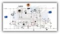
In a circuit like the one below, how is it possible that the voltage and current are both controlled by the IC feedback pin?
I am thankful with your guidance
 

Attachments

Papabravo

Joined Feb 24, 2006
22,058
The FB pin is one of the inputs to an error amplifier. The ouput voltage is controlled by adjusting the duty cycle. An increase in the duty cycle allows more current to charge the inductir and raises the average current delivered to the load which in turn uncrease the output voltage. When the dyty cycle is reduced there is less time for the input curren to charge the inductor and the average current is reduced and the output voltage is also reduced.

See the following article
Buck converter - Wikipedia.

See fig. 4 for a picture of the current wavefoms. In each cycle there will be a minimum current, and a maximum current. There is als an average current. The difference between the maximum and the minimum is called the ripple current and 20% of the average current is a typical for a ripple current in CCM (Continuous Conduction Mode).
 

ronsimpson

Joined Oct 7, 2019
4,647
is it possible that the voltage and current are both controlled by the IC feedback pin?
In normal operation, the FB pin looks at the output voltage. (R2 & R1 divide down the voltage)
In current limit mode, R 0.05R is the current shunt. IC1A looks at the voltage across the shunt resistor. Too much current results in the voltage across the shunt to be higher than the voltage from R9. This causes IC1a to pull up on the FB pin, via a diode or LED. With the FB pin being too high the duty cycle will drop to zero. The control loop stops looking at the output voltage and looks only at the current. The duty cycle will be reduced to hold the current constant and let the voltage fall.
1672514019799.png
 

Thread Starter

mrh586

Joined Dec 5, 2021
90
The FB pin is one of the inputs to an error amplifier. The ouput voltage is controlled by adjusting the duty cycle. An increase in the duty cycle allows more current to charge the inductir and raises the average current delivered to the load which in turn uncrease the output voltage. When the dyty cycle is reduced there is less time for the input curren to charge the inductor and the average current is reduced and the output voltage is also reduced.
Thank you
If you mean that as the voltage decreases, the current also decreases or vice versa, I have seen videos of testing this circuit that while the voltage is constant, the current increases or decreases, or the constant current and voltage decreases and increases. to be
 

Ian0

Joined Aug 7, 2020
13,097
The XR4016 increases or decreases its m/s ratio to keep the feedback input at 1.25V.
If you remove the opamps, you have a simple voltage regulated output determined by the ratio of R1 and R2.
IC1a compares the voltage across the 50mΩ sense resistor with the voltage on R5. If it is too high it increases the voltage on R1 (via the LED) to cause the XR4016 to reduce its output.
 

Thread Starter

mrh586

Joined Dec 5, 2021
90
In normal operation, the FB pin looks at the output voltage. (R2 & R1 divide down the voltage)
In current limit mode, R 0.05R is the current shunt. IC1A looks at the voltage across the shunt resistor. Too much current results in the voltage across the shunt to be higher than the voltage from R9. This causes IC1a to pull up on the FB pin, via a diode or LED. With the FB pin being too high the duty cycle will drop to zero. The control loop stops looking at the output voltage and looks only at the current. The duty cycle will be reduced to hold the current constant and let the voltage fall.
Thank you
If I understand correctly, the type of pulse that reaches the feedback through resistive division is different from the pulse that the output pin of the op amp gives to the feedback.
Is this impression correct?
 

Thread Starter

mrh586

Joined Dec 5, 2021
90
The XR4016 increases or decreases its m/s ratio to keep the feedback input at 1.25V.
If you remove the opamps, you have a simple voltage regulated output determined by the ratio of R1 and R2.
IC1a compares the voltage across the 50mΩ sense resistor with the voltage on R5. If it is too high it increases the voltage on R1 (via the LED) to cause the XR4016 to reduce its output.
Thank you
I want to know what is the difference between the voltage sent from pin 1 of the op amp (and LED) and resistor R2?
 

MrChips

Joined Oct 2, 2009
34,628
Let's understand what current and voltage control means.
You cannot control both current and voltage at the same time. The two are interrelated according to Ohm's Law:

I = V / R
V = I x R

Hence for a given load R, I is proportional to V.

Current and voltage settings on a PSU (power supply unit) are limits. They set the maximum current and voltage, whichever comes first.
If the voltage limit is reached the PSU is in constant voltage mode.
If the current limit is reached the PSU is in constant current mode.
You cannot be in both modes at the same time.
 

Papabravo

Joined Feb 24, 2006
22,058
You also need to distinguish between instantaneous current and average current. In a buck converter, the instantaneous current in the inductor rises and falls on each switching cycle. It is never constant. It is the average current that is deliverd to the load. The value of the inductor and the switching frequency determine the magnitude of the current ripple in the inductor. The output capacitor and the switching frequency determine the voltage ripple on the load.
 

Ian0

Joined Aug 7, 2020
13,097
Thank you
I want to know what is the difference between the voltage sent from pin 1 of the op amp (and LED) and resistor R2?
I'm not sure that's a useful question to ask.
If the current is too high the LM358 will be able to put 3.5V minus the LED forward voltage on the feedback pin (say 1.8V), but if the feedback pin goes over 1.25V for any length of time, the output will shut down.
 

ronsimpson

Joined Oct 7, 2019
4,647
If I understand correctly, the type of pulse that reaches the feedback through resistive division is different from the pulse that the output pin of the op amp gives to the feedback.
"pulse" The output voltage gets divided down to 1.25V for the FB pin. The voltage on the FB pin should be 1.25V. If the voltage is slightly lower the duty cycle increases. If the voltage is higher the duty cycle drops. There is no pulse. (if the output is 12V the divider will hand the IC 1.25V)
The IC really does not have an over current input. So, the op-amp pulls up the FB pin to trick the IC into thinking the voltage is too high. This is how current limit is done.

If you look at the picture below, the IC does have an over current function but it is not adjustable. It is all inside and it is there more to save the IC and inductor. There is no knob to make adjustments.
1672524790559.png
 
Top