How do you adjust both voltage and amperage independantly? Like on a welding machine?

MrChips

Joined Oct 2, 2009
35,025
On any and all kinds of power supplies you cannot control the output voltage and current independently.
What you are selecting on the control knobs are the maximum limits of voltage and current.

If the maximum current limit is reached the power supply becomes a constant current supply.
If the maximum voltage limit is reached the power supply becomes a constant voltage supply.
 

Thread Starter

born2dive00

Joined Oct 24, 2016
285
Ok I found out how to make a 5a power unit like R!F was talking about,
and I got all the materials In my house from another project. (looks real professional too) But it is limited to 30v at 6A and it has only a course adjustments.

1. how do I make the fine tune gain that I need. the video shows a course gain (as I under stand it)
2. my concern on the low voltage side is that the unit might not be fine enough, any way to make sure that the unit could get accurate voltage at low amps?
3. below is the table for the different Nichrome wires I will be using) I need voltages range from.8 to 71.5 volts and from 1 to 5.61 Amps, So how do I get the higher voltages needed? can I simply create a transformer, with a metal rod (say 10 wraps of wire on one side and 20 on the other) to drop the amps and double the voltage?
I was thinking of adding a high low switch on the Ltc3780 buck up/down converter that would allow me to take the voltage from lct 3780 and send it to this unit http://www.ebay.com/itm/600W-DC-DC-...722860?hash=item1a257743ec:g:IIAAAOSwX9FZJ~8V
This would allow me (I believe to take 30vdc and bump it up to the 71.5v @1.32a I would need safely.) then just flip the switch to low position to use the 0-30v. would this work?

30 gauge -10% = 3" 6" 12" 24" 36" 48" 60" 72" 96" +10%=
V@A 2@.8 2.2@1.0 4@1.18 8@1.13 16.2@1.2 24.5@1.20 32@1.197 40@1.18 49@1.20 65@1.2 71.5@1.32
24 gauge 3" 6" 12" 24" 36" 48" 60" 72" 96"
V@A 1.2@2.87 2.4@2.87 5@2.87 9.6@2.9 14.7@2.91 19.2@2.9 24.2@2.89 29@2.87 39@2.9 42.9@3.19
20 gauge 3" 6" 12" 24" 36" 48" 60" 72" 96"
V@A .8@4.85 1.7@5.15 3.4@5.15 6.8@5.15 10.1@5.07 13.7@5.11 16.7@5.06 20.3@5.09 27@5.10 29.7@5.61
 
Last edited:

drc_567

Joined Dec 29, 2008
1,156
... Something easy to try out ... a variable AC choke, or inductor.
.. It is simply a substantial coil of wire, maybe wrapped around a length of PVC as a guide. It would be placed in series with the secondary of a power transformer, in line with the nichrome heating element. In order to change the load/heater voltage and current, an iron rod ... something like a piece of rebar, is inserted into the center of the coil form. The iron rod serves to increase the inductive reactance across the coil, which decreases the voltage across the heating element/load.
... I saw this method described in a textbook. It was described as a way to control the heat intensity of an AC clothes iron ... back when clothes needed ironing.
... something to try out ...and see how it works.
 

tcmtech

Joined Nov 4, 2013
2,867
If it was me I would just use a variac and appropriate step down transformer then put a AC current meter in series with the heating wire then just adjust the input voltage up or down to match whatever the current wire needs for its relative size.

No need to over complicate a simple heater.
 

Thread Starter

born2dive00

Joined Oct 24, 2016
285
Hello All,

How do I wire 2 pots to get a course and fine adjustment, I have a 500k ohm pot, and a 50k ohm for the voltage, on the circuit, I have a 200k ohm and a 20k ohm pot for the current. I am replacing the on board pots on the LCT3780 converter. to remote pots.
 

#12

Joined Nov 30, 2010
18,224
How do I wire 2 pots to get a course and fine adjustment
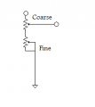
Put them in series with each other. Start with the fine adjustment centered. Get close with the coarse adjustment and then adjust the other pot.
I would like to emphasize that nichrome does not care about AC vs DC. I disagree with the idea that a fine adjustment is useful. The wire is going to change temperature when it touches the load, anyway. I would minimize that by using a fairly heavy nichrome at low volts and high current. It isn't as difficult as you seem to think it is. I'm sure that experience will get you adjusted rather quickly.
 

Thread Starter

born2dive00

Joined Oct 24, 2016
285
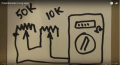
Hey #12 good to see you again, Is this correct for series on a potUntitled.png

I would be replacing the 50k with a 500k and the 10k with a 50k for the voltage
I would be replacing the 50k with a 200k and the 10k with a 20k for the current
does that sound like it will give me decent adjustments?

As far as the fine adjustments, with the nichrome wire, I have literally exploded 3" nichrome wire (hot wire shards in the scalp is not fun) several times by passing too much voltage and or too much amperage thru the wire due to MFG defects in the wire, (too much sulphur / carbon content) I want very fine control so I can optimum temps. You would not believe what +- 1 or 2 degrees F make in cutting smooth foam in removing spider webbing.

I also use use high density Styrofoam pallets for my wings and fuselage, it is really heavy not like the Styrofoam cup or depron stuff. You can hit this stuff at full force with a sledge hammer and it will barely make a dent. There is no need to sheet it, just run a 2oz fiberglass over it and your are done.

You hollow out the areas where you don't need the extra weight..With this stuff, I can stand on a lightened wing without breaking it. 200mph flying wings no problem. 2 carbon fiber rods to join the wing halves that's it.


Put them in series with each other. Start with the fine adjustment centered. Get close with the coarse adjustment and then adjust the other pot.
I would like to emphasize that nichrome does not care about AC vs DC. I disagree with the idea that a fine adjustment is useful. The wire is going to change temperature when it touches the load, anyway. I would minimize that by using a fairly heavy nichrome at low volts and high current. It isn't as difficult as you seem to think it is. I'm sure that experience will get you adjusted rather quickly.
 

#12

Joined Nov 30, 2010
18,224
does that sound like it will give me decent adjustments?
Yebbut, the exact shape of the circuit depends on what you're controlling. I assumed your adjuster would be on a voltage regulator chip, so I wouldn't do it as a rheostat configuration like you drew. If you are using something like 500 watt ceramic pots in series with the load, the rheostat shape is correct.
 

Thread Starter

born2dive00

Joined Oct 24, 2016
285
I am replacing the pots on this circuit
http://www.ebay.co.uk/itm/LTC3780-A...ltage-step-up-step-down-12v-24v-/301606607026

and on this circuit
http://www.ebay.com/itm/201932553346

Yebbut, the exact shape of the circuit depends on what you're controlling. I assumed your adjuster would be on a voltage regulator chip, so I wouldn't do it as a rheostat configuration like you drew. If you are using something like 500 watt ceramic pots in series with the load, the rheostat shape is correct.
 

#12

Joined Nov 30, 2010
18,224
Both of those have tiny trim pots on the board so it seems the configuration of the adjustments has already been determined. I'm betting one end of the controls is grounded, as in, "not a rheostat configuration". Just take out the provided pot, place two in series, and you're done. It will probably turn out like this:Fine adj.png
 

Thread Starter

born2dive00

Joined Oct 24, 2016
285
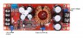
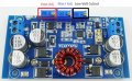
Here are the photos of the circuits labled
I assume that the pot with the 504/506 are 500k ohm pots correct?
I assume that the pots with the 204 are 200k ohm pots correct?
s-l1600.jpg LTC3780_WD2002SJ.jpg
Yebbut, the exact shape of the circuit depends on what you're controlling. I assumed your adjuster would be on a voltage regulator chip, so I wouldn't do it as a rheostat configuration like you drew. If you are using something like 500 watt ceramic pots in series with the load, the rheostat shape is correct.
 

Thread Starter

born2dive00

Joined Oct 24, 2016
285
Can you please explain the diagram more, as I must remote mount the pots on the box and run wires to the boards.
I know that the triangle is Ground but what do the 2 circles mean??

It looks like 1 leg from the course pot is connected to a leg on the fine pot, and that the center leg on the fine pot and the right leg are bridged together????

Both of those have tiny trim pots on the board so it seems the configuration of the adjustments has already been determined. I'm betting one end of the controls is grounded, as in, "not a rheostat configuration". Just take out the provided pot, place two in series, and you're done. It will probably turn out like this:View attachment 127787
 

#12

Joined Nov 30, 2010
18,224
what do the 2 circles mean??
The two circles mean, "attach to circuit here". Each trimpot which is already on the board has three legs. My drawing has three places to attach to the board. Did you find some extras?

I know what it looks like. It looks like exactly what I expect to happen. That is as far as I can speculate without having the boards in my hand.
 
The Vout Ajdust POT is a 10 turn POT with likely, two of the terminals shorted together (hopefully). Even if it's not it will likely still work as #12 noted.

You would not remote mount those pots, but rather NEW pats that are designed for panel mounting. You can equip these with turns counting dials. The 504 means it's a 500,000 ohm (500K) pot for Vadj.

Here http://www.ebay.com/itm/10K-Ohm-359...127367?hash=item1a18f91787:g:NXwAAOSwo4pYhbeS is an example of a 10K pot.
 

Thread Starter

born2dive00

Joined Oct 24, 2016
285
So if I got you correct with the diagram it should look like this?

r-v10kl-bp-fnd_topdown1_1.png


Both of those have tiny trim pots on the board so it seems the configuration of the adjustments has already been determined. I'm betting one end of the controls is grounded, as in, "not a rheostat configuration". Just take out the provided pot, place two in series, and you're done. It will probably turn out like this:View attachment 127787
 

Thread Starter

born2dive00

Joined Oct 24, 2016
285
What is the difference between my drawing and your drawing as far as functionality?

Both of those have tiny trim pots on the board so it seems the configuration of the adjustments has already been determined. I'm betting one end of the controls is grounded, as in, "not a rheostat configuration". Just take out the provided pot, place two in series, and you're done. It will probably turn out like this:View attachment 127787
 

Thread Starter

born2dive00

Joined Oct 24, 2016
285
The pots on the circuit are easily removed and replaced with a 500k I believe. I have switched one out before and it works well with a standard pot, I just need more fine tuning. as far as the 10 turn pots, that wont work as I need almost instantainous turn down in some situations. which are not too easy to do with the vanier pots.
also I am adjusting voltage and current not just volts
appreciate the thought though.

The Vout Ajdust POT is a 10 turn POT with likely, two of the terminals shorted together (hopefully). Even if it's not it will likely still work as #12 noted.

You would not remote mount those pots, but rather NEW pats that are designed for panel mounting. You can equip these with turns counting dials. The 504 means it's a 500,000 ohm (500K) pot for Vadj.

Here http://www.ebay.com/itm/10K-Ohm-359...127367?hash=item1a18f91787:g:NXwAAOSwo4pYhbeS is an example of a 10K pot.
 

Thread Starter

born2dive00

Joined Oct 24, 2016
285
Both of those have tiny trim pots on the board so it seems the configuration of the adjustments has already been determined. I'm betting one end of the controls is grounded, as in, "not a rheostat configuration". Just take out the provided pot, place two in series, and you're done. It will probably turn out like this:View attachment 127787
Hello again 12, On your drawing which pot is the course, the 500k or the 50k? is my drawing correct to your drawing?
 
Top