 Facebook
 Google
 GitHub
 Linkedin
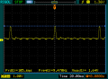
How do I simulate this waveform in LTSpice?
I don't care so much about the noise but it would be nice. I can get a pulse to look close but this is a bit more half sinusoidal than a square pulse.

I don't care so much about the noise but it would be nice. I can get a pulse to look close but this is a bit more half sinusoidal than a square pulse.
Attachments
-
 3.3 KB Views: 7

")


