Facebook
 Google
 GitHub
 Linkedin
I'm trying to interface a 5V digital signal to drive an ultrasound transmitter. I've seen several approaches including this thread from a few years back.
http://forum.allaboutcircuits.com/t...rt-voltage-from-0-to-5v-into-10-to-10v.62652/
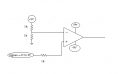
My current circuit will only go from -3V to 8V and I don't understand how to debug it. I'm guessing it has to do with the voltage divider based reference. I don't need to operate in the linear region. Is there a simpler and better way to do this? I've also tried the circuit in the second attachment without success even though my LTSpice simulation gave the results I wanted. As you can tell my analog skills are really weak.


Any help would be appreciated.
Thanks,
Lane
http://forum.allaboutcircuits.com/t...rt-voltage-from-0-to-5v-into-10-to-10v.62652/
My current circuit will only go from -3V to 8V and I don't understand how to debug it. I'm guessing it has to do with the voltage divider based reference. I don't need to operate in the linear region. Is there a simpler and better way to do this? I've also tried the circuit in the second attachment without success even though my LTSpice simulation gave the results I wanted. As you can tell my analog skills are really weak.
Any help would be appreciated.
Thanks,
Lane