Facebook
 Google
 GitHub
 Linkedin
We have a project coming up in my Engineering Drafting and Design class and I don't have much idea yet on how to accomplish it. We are tasked to combine different circuits to design one complete device. Then we need to of course make the Schematic (and simulate it), as well as creating the PCB. I have no problems with using the software to accomplish them. I just don't know how to do the actual design... As we only did this class for 6 weeks so I don't have proper understanding of circuits and have to rely on YT tutorials.
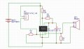
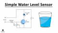
My idea is to combine a Battery Monitoring circuit , Water Level Indicator circuit, and a Police Siren Circuit all together to form a one complete functional system that has multiple features.
Attached are the individual circuits (I found them on several websites):
As you can see, they are three different circuits. I need to combine them into one. It's no problem to go look for circuits on the internet as the main objective of my class is to improve software skills. However, how can I combine the three of them? Of course I have to modify the components but that's all I know. Not sure how to make it work.
Source/s:
Battery Monitoring Circuit:
https://circuitdigest.com/electronic-circuits/battery-monitor-circuit
Water Level Indicator Circuit:
https://circuits-diy.com/simple-water-level-indicator-circuit/
Police Siren Circuit:
https://www.electronicshub.org/police-siren-circuit-using-ne555-timer/
Attachments
-
 24.8 KB Views: 19
 -
 106.3 KB Views: 19
 -
 72.9 KB Views: 19
Last edited: