I'm trying to repair a floor fan that seized up.
I've got all of the galling removed, and the motor spins freely.
The fan still doesn't work, and I suspect the capacitor, it is a CBB61.
How do I test it?
Short across the capacitor leads to discharge it completely.
When the short is removed, it should take approximately 3 seconds to get within 4/5 of the supply voltage. If it's a lot less than 3 seconds, the cap is open. If it never comes up near the supply voltage, it may have excessive leakage current.
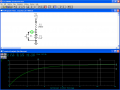
I'm not sure what I'm looking at in the drawing.
My fan capacitor has two wires coming out of it.
I can see that V1 is 10 volts positive, coming in to the resistor, and then the resistor hooks up to one wire of the capacitor. I'm guessing the 10 volts negative of the power supply then hooks into the other wire of the capacitor?
I don't have a switch, should I add one into my circuit?
I'm not sure what I'm looking at in the drawing.
My fan capacitor has two wires coming out of it.
I can see that V1 is 10 volts positive, coming in to the resistor, and then the resistor hooks up to one wire of the capacitor. I'm guessing the 10 volts negative of the power supply then hooks into the other wire of the capacitor?
SgtWookie,
Here are the new stats, using the 2uF, with 9v PS
I set my meter to read 10ths instead of just whole numbers.
These are interesting enough that I will go back and retest the first cap later.
1 sec = 4.8v
2 sec = 6.8v
3 sec = 7.8v
4 sec = 8.4v
5 sec = 9.3v
6 sec = 9.6v
7 sec = 9.7v
8 sec = 9.8v
9 sec = 9.8v
10 sec = 9.9v
They sound pretty close to what they should be. It's hard to be accurate for the shorter time periods, particularly if you're flipping switches manually.
One thing you really can't test them for without more equipment is leakage at the rated voltage.
When checking capacitors, a general rule is that 5 time constants (RxC) will take you to about 98% of the final charge or discharge figure. This also applies to inductors as well. With a votmeter or a scope, you can easily test this rule.
 Facebook
 Google
 GitHub
 Linkedin