 Facebook
 Google
 GitHub
 Linkedin
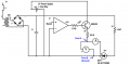
I'm a novice. I'd like to know how to measure and calculate the current & volts which trigger a mosfet or SCR gate in a schematic like the one attached. A signal comes in to the opamp and sends the output high, this switches the transistor Q1 and it triggers the gate of the SCR. Is the voltmeter placed from the Point A to B properly placed to measure the voltage that ends up being applied to the gate? By experiment it reads 880mV.
How do I calculate the amps and volts so I can cross check it by experiment. For example If I = V/R, then current = 5V/150 = 33mA. Should the ammeter show 33mA being applied to the gate?
Can the base of Q1 (from the opamp) change the 5V from the power supply? I might not be getting a full 5V to resistor R5 correct?
Attachments
-
 32.3 KB Views: 52


