How can you know if a buck converter has backflow protection ?

Thread Starter

nulik

Joined Mar 4, 2021
16
I have a few buck converters (step down , buck-boost and boost) and I would like know if the circuit of the buck converter includes anti-backflow protection or not, so I could avoid adding a diode(on the output) in case it already has it. I am going to connect it to a 300A battery bus, so this knowledge is critical in order to avoid an arc-flash and burning the fingers.

How do I do it?

Someone suggested to use a multimeter when no-load / no current is present in the device, but I don't understand where do I connect multimeter probes and how do I interpret the results?

For example, I connected one probe to positive output, another to positive input, and I got current flowing for 2 seconds (with green light flashing). After that I got 0L. What does this mean? Or better said, what is the correct procedure to test this ?
 

Papabravo

Joined Feb 24, 2006
22,105
Can you show us an example schematic where "backflow" is possible. I would be interested in simulating such a circuit to confirm that fact.
 

Thread Starter

nulik

Joined Mar 4, 2021
16
What are you trying to do?

What are the voltages involved?
Why do you think "backflow" is a problem?
For example, I have a 550 watt solar panel on the input (many of them in parallel, could be the case), and a Lithium Iron Phosphate battery on the output. When the buck converter doesn't have any current on the output (it is night, or the solar panel is disconnected) the battery will put current on the outputs of the buck , because battery has current flowing both directions (common port configuration, in particular). When you charge the battery, current flows towards the battery, when you discharge it, current flows in the reverse, and the buck converter is connected to this bus (where all batteries are shared), and works as a charger. So backflow can burn the buck if it is not designed to deal with current flowing towards the output inside the buck.
Voltage: 29V when 100% charged, 26V when 50% charged


Can you show us an example schematic where "backflow" is possible. I would be interested in simulating such a circuit to confirm that fact.
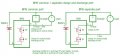
Attached image for reference (I am using the circuit on the left side (common port), so just insert the buck converter in the square box that is labeled "Charger"
 

Attachments

Last edited:

Papabravo

Joined Feb 24, 2006
22,105
You can get away with almost anything when you eliminate all the useful details. Am I to understand that the circuit breaks when the battery is full and when it is empty. It only works when the state of charge is between full and empty. That doesn't make a lot of sense, and it says nothing about how you expect "backflow" to happen. Your slides may work for unsophisticated investor presentations, but as engineering documents they are crap.
 
Top