Facebook
 Google
 GitHub
 Linkedin
Hi,
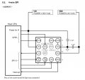
I'm making PCBs for AK8963C chips, shown here: https://forum.allaboutcircuits.com/...ectronic-errors-oshonsoft.187539/post-1741319
When I've soldered them onto the PCB, obviously I can't check the balls as they are under the chip, so how are these type of chips tested, after soldering?
So far I've used a meter and continuity mode and diode mode. With diode mode, I connect the +V lead to GND, and check the tracks in turn, if there is no result, I either swap the leads around, or switch to continuity mode. Usually, I get some reading, which isn't open or short. Today I made 9x PCBs 5x good 4x bad.
EDITED.
Cheers, Camerart.
Last edited: