Facebook
 Google
 GitHub
 Linkedin
In my project, I need to make current amplifier which have < 2mA input current and > 100 mA output current.
Actually, I want to fully understand the BJT circuit, and then making a proper amplifier circuit.
But project deadline is soon, so I just want to make the amplifier first.
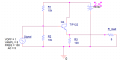
present circuit with two TIP122 (NPN BJT) is follow,

My goal is applying the linearly amplified AC current (100~200 mA) in R_load.
The problem is ...
- Signal source have current limitation ( maximum current : 2 mA, maximum voltage : -10 ~ +10 V ).
- R3 have big DC current so, It is easily heated.
- non-linearly amplified...
So, can you suggest proper amplifier circuit for this situation?
If you give some circuit scheme with detail parameter ( Ohm, Volts, Capacitance, etc. ), would be perfect!
Thank you!
// summary
with 2 TIP 122,
- Input AC signal : -10 V ~ +10 V sine wave (current limit ~ 2mA).
- output AC signal : linearly amplified sine wave ( 100~ 200 mA )
Actually, I want to fully understand the BJT circuit, and then making a proper amplifier circuit.
But project deadline is soon, so I just want to make the amplifier first.
present circuit with two TIP122 (NPN BJT) is follow,
My goal is applying the linearly amplified AC current (100~200 mA) in R_load.
The problem is ...
- Signal source have current limitation ( maximum current : 2 mA, maximum voltage : -10 ~ +10 V ).
- R3 have big DC current so, It is easily heated.
- non-linearly amplified...
So, can you suggest proper amplifier circuit for this situation?
If you give some circuit scheme with detail parameter ( Ohm, Volts, Capacitance, etc. ), would be perfect!
Thank you!
// summary
with 2 TIP 122,
- Input AC signal : -10 V ~ +10 V sine wave (current limit ~ 2mA).
- output AC signal : linearly amplified sine wave ( 100~ 200 mA )
Attachments
-
 58.3 KB Views: 4