Facebook
 Google
 GitHub
 Linkedin
Hello,
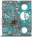
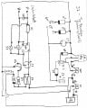
First post here. I've aquired a small Honda portable generator (vintage 1977). The model is EG 1500 (1.5kw output). This generator is equipped with an automatic voltage regulator (avr) that is physically damaged. This particular avr uses the input of 120vac from the stator and apparently rectifies it for use as an output to the brushes to control rotor field current and therefore voltage output. Frequency appears to be regulated by engine rpm and does not appear to be controlled by the avr. The avr assembly is filled with what I believe to be fiberglass resin (or similar) material to seal all the components. This stuff is very difficult to remove and I don't think I can do it without destroying all the internal components. Honda no longer services this regulator and the universal ones are quite expensive. I'd like to recreate a suitable circuit to regulate the generator as a project for my own learning. At a minimum, I would need to rectify 120vac and use the the corresponding dc to drive the rotor field current to maintain 120vac under varying loads. Rotor resistance is 54 ohms. There is also an external cap of 200uF 250WV attached to the original avr. There are 4 wires from the stator for input to the avr (althought I'm not sure all would be required) and the coresponding 2 dc output wires from the avr to the rotor brushes. Any suggestions would be appreciated.
First post here. I've aquired a small Honda portable generator (vintage 1977). The model is EG 1500 (1.5kw output). This generator is equipped with an automatic voltage regulator (avr) that is physically damaged. This particular avr uses the input of 120vac from the stator and apparently rectifies it for use as an output to the brushes to control rotor field current and therefore voltage output. Frequency appears to be regulated by engine rpm and does not appear to be controlled by the avr. The avr assembly is filled with what I believe to be fiberglass resin (or similar) material to seal all the components. This stuff is very difficult to remove and I don't think I can do it without destroying all the internal components. Honda no longer services this regulator and the universal ones are quite expensive. I'd like to recreate a suitable circuit to regulate the generator as a project for my own learning. At a minimum, I would need to rectify 120vac and use the the corresponding dc to drive the rotor field current to maintain 120vac under varying loads. Rotor resistance is 54 ohms. There is also an external cap of 200uF 250WV attached to the original avr. There are 4 wires from the stator for input to the avr (althought I'm not sure all would be required) and the coresponding 2 dc output wires from the avr to the rotor brushes. Any suggestions would be appreciated.