Hit and hold circuit for solenoid valve

crutschow

Joined Mar 14, 2008
38,629
But now consider the offerings using an opamp, which require a whole power supply.
The CMOS circuit in post #9 does an automatic PWM hit-and-hold, and draws very little power (<1mA) so would require just a very simply resister-Zener or IC supply.
(Is that still considered a "whole power supply"?)
 
Last edited:

MisterBill2

Joined Jan 23, 2018
27,905
The dissipation in the regulator IC is why I suggested the RC scheme. The power wasted in the resistor will be about the same as the power wasted in the 7805, and the externals will be much smaller, because really, the current requirement starts dropping as soon as the core in the solenoid starts moving, and so the capacitor only needs to be large enough to require a few milliseconds to charge. Also, there is no reason at all for the holding voltage to be regulated to exactly 5.0 volts. 6 volts will work as well, and as the coil heats the resistance will rise and the current will drop a bit more.
 

vu2nan

Joined Sep 11, 2014
357
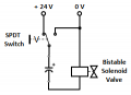
Here's a simple solution that employs a bi-stable solenoid valve and an electrolytic capacitor.

123.png

In one position of the switch, the capacitor charges through the solenoid.

In the other position, the capacitor discharges through it.

In other words, the solenoid valve is set / reset by the capacitor charge / discharge pulses.

The pulse width (time constant RC) is determined by the capacitance and the solenoid resistance.

Nandu.
 
Last edited:

MisterBill2

Joined Jan 23, 2018
27,905
Here's a simple solution that employs a bi-stable solenoid valve and an electrolytic capacitor.

View attachment 289963

In one position of the switch, the valve is set as the capacitor charges through the solenoid.

In the other position, the valve is reset as the capacitor discharges through the solenoid.

In other words, the solenoid is operated by the capacitor charge / discharge pulses.

The pulse width (time constant) is determined by the capacitance and solenoid resistance.

Nandu.
While I am certain that such bi-stable solenoid valves must exist, They would never be included in any application where safety demanded positive shutoff or where staying on would lead to property damage, such as flooding.
And certainly they would not eve be used in a fuel control system.
And the arrangement shown in the post will fail because of capacitor self -discharge will leave the capacitor with no energy left to operate the valve after a few minutes.
 

BillB3857

Joined Feb 28, 2009
2,573
Back in the dark ages when we were using punched tape readers (remember those) we had a problem with the brake magnet coils on tape brakes burning up. These brakes needed to grasp the tape to prevent it from overshooting the END OF BLOCK character. Our solution was to insert a large electrolytic capacitor, bypassed by a suitable resistor, in series with the brake coil. The capacitor provided an inrush current to apply the brake quickly, thus avoiding overshoot, then quickly charged up and allowing only the current that was limited by the resistor to provide enough current to hold the tape. No micro controller involved.
 

Thread Starter

Juancho_mkrk

Joined Feb 27, 2023
4
But it likely is.
Have you calculated the power dissipated by the 7805, which is the voltage drop across it times the current (hint: it's about 3W).
Is the 7805 on a decent heat-sink?
Thanks to all. I have planned a dissipation system for the final design, but I didn't think it would cause me problems since the prototyping stage. In fact, crutschaw, the actual maximum current currently flowing through the 7805 is no more than 150mA. Once the heatsink was installed, everything worked perfectly.

Thanks and this thread will be considered closed.
 
Top