High Voltage Rectifying

Thread Starter

rwfwef

Joined Sep 14, 2025
68
Hi,

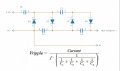
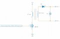
I'm currently trying to rectify 1.3kV and was looking for some advice. I'll put a simplified circuit diagram in attachments.

Specs:

Vin = 12V
Iin = <2A
Np = 5 Turns
Ns = 550 Turns
Nratio = 1:110
Vout = 1320V?
Frequency = 185KHz
Duty Cycle 50%

For rectifying, should I use the configuration I have in the circuit diagram and also any advice on what diode to use, capacitance, etc?
 

Attachments

ronsimpson

Joined Oct 7, 2019
4,645
Frequency = 185KHz
To make this work at 185khz you need to understand transformers and diodes at high frequency.
Diodes are slow at high voltage. Try to keep the diode voltage under 1kv.
Transformers resonate at some frequency. Putting that many turns in one pile causes then to operate slow.

I suggest breaking up the secondary into 5 different windings using lower voltage diodes.
1762375227991.png
 

Thread Starter

rwfwef

Joined Sep 14, 2025
68
To make this work at 185khz you need to understand transformers and diodes at high frequency.
Diodes are slow at high voltage. Try to keep the diode voltage under 1kv.
Transformers resonate at some frequency. Putting that many turns in one pile causes then to operate slow.

I suggest breaking up the secondary into 5 different windings using lower voltage diodes.
View attachment 358314
Let's say my frequency were around 50KHz, would that still be necessary? Also could I not just stack a bunch of high speed diodes in the series for example: if I put 3, UF5408 diodes in series?
 

Thread Starter

rwfwef

Joined Sep 14, 2025
68
Or what if I run it through a half wave voltage multiplier (capacitor and diode)? I wouldn't mind having a higher voltage output anyway. Would that work?
 
Last edited:

Thread Starter

rwfwef

Joined Sep 14, 2025
68
That is a good 75nS diose. Do you really need a 3A diode? I often use the 1A version of that diode.
It is fine to stack diodes.
You could make two 600V windings using 1kv diodes.
The capacitor multiplier is very common.
Lets say I go with a capacitor diode multiplier, and I use UF4007 x2 in series which would be good for 2kV, would it still be necessary to have 2 separate 600V output windings (the transformer is already wound)? Also goes without saying high voltage rated capacitors. I don't care too much for power losses, just want to get high voltage DC with a decently low voltage ripple. Maybe a voltage ripple 0.01% of the actual voltage.
 

ronsimpson

Joined Oct 7, 2019
4,645
UF4007 are good.
If the transformer is wound use it. It would be nice to know its resonant frequency. That will tell you how fast you can go.
Are you using the transformer in flyback mode for feed-forward? (phasing on the transformer)
 

Thread Starter

rwfwef

Joined Sep 14, 2025
68
UF4007 are good.
If the transformer is wound use it. It would be nice to know its resonant frequency. That will tell you how fast you can go.
Are you using the transformer in flyback mode for feed-forward? (phasing on the transformer)
The reason I'm using 185KHz is because after tuning it using an adjustable PWM, around that frequency is where it ran well. Good arcs, and wasnt tripping the short circuit protection on my power supply.

In terms of the transformer, its an double E core un-gapped

In terms of capacitance for the capacitors in the voltage multiplier, is higher capacitance generally better? And I assume that I should go 2kV + rated capacitors as well?

Also I played around the frequency and between 180KHz-192KHz looked to be the best in terms of long arcs. The voltage across the primary coil was at its highest over 200KHz but the arcs were horrible. So I'm thinking that as long as I'm in the 180KHz-192KHz range, it should be fine.
 
Last edited:

Thread Starter

rwfwef

Joined Sep 14, 2025
68
In terms of capacitance for the multiplier, would 78nF be alright, or is that too low? Or too high and I can use a smaller cap? It goes without saying that I'm keeping in mind the voltage that would go across it so I'm planning on going at 2kV rated if not higher.

Pin for the circuit is max 24W
 
Last edited:

BobTPH

Joined Jun 5, 2013
11,463
In terms of capacitance for the multiplier, would 78nF be alright, or is that too low? Or too high and I can use a smaller cap? It goes without saying that I'm keeping in mind the voltage that would go across it so I'm planning on going at 2kV rated if not higher.

Pin for the circuit is max 24W
The ripple depends on the capacitance, frequency and current. 0.01% ripple is quite a stringent requirement, why must it be so low?
 

Thread Starter

rwfwef

Joined Sep 14, 2025
68
The ripple depends on the capacitance, frequency and current. 0.01% ripple is quite a stringent requirement, why must it be so low?
I want it low because I'm planning on turning it into pulsing dc or ac at a different frequency. Does the voltage ripple formula apply even when using a half-wave voltage multiplier? And if that's the case then am I calculating based on all the capacitors in the voltage multiplier? Example in attachments

Also input is 1.3kV at 185KHz
 

Attachments

Last edited:

neonstrobe

Joined May 15, 2009
199
YOu need to be careful with a flyback (I assume that is the operating mode from the labels on the winding).
And avoid saturating the transformer.
Check out the inductance, and therefore maximum current at your operating frequency, and whether that saturates the core.
You are hoping, unless your diagram did not include a de-mag winding, that the secondary will fully demagnetise the core in the "off" period.
If it does not demag then the effective inductance next time will be lower, the current higher and so on. Your Fet may then be expired.
 
Top