High Voltage H-Bridge for DC Motor

Thread Starter

nikos_asi

Joined Feb 12, 2025
13
Hello to all,

I am modifying a machine which has a 300V DC Motor 500W which I want to make it to work bidirectional, CW and CCW.
The motor has two wires +-.
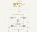
It will have a PWM control with a TL494 and I would like to make the bidirectional circuit using Mosfets in H-Bridge configuration.

I choose the IRFP460LC N-channel and IXTH20P50P P-Channel mosfets.
The PWM signal will go to small relay which I will use it with a footswitch and will send the PWM signal to the mosfet. With this way I would like to change the direction of the motor.
I designed the H-Bridge circuit but I'm not sure if it will work.
Please, can you tell me based on your expoerience if it will work as I would like?

Thank you in advance!
All the best,
Nikos
 

Attachments

ronsimpson

Joined Oct 7, 2019
4,647
The MOSFETs are turned on when a voltage is applied from G to S (pins 1-3). The voltage is usually in the 6V to 20V range. (depends on the part) If the voltage is more than 20V the part will break.
There needs to be a different way to drive the top Gates. Look at bridge Gate driver ICs. Or top FET drivers.
1739409219953.png
 

LowQCab

Joined Nov 6, 2012
5,101
A PWM Controller would be a good idea,

You have the possibility of going from Full-Speed-Forward to Full-Speed-Reverse instantly.

This can possibly break things like Gears and Shafts,
and, in any case, it is very hard on the Motor,
and, it may blow Fuses because of extremely high start-up Currents..

Please provide a complete description of your 300-Volt DC Power-Supply,
preferably a complete Schematic.
.
.
.
 

Thread Starter

nikos_asi

Joined Feb 12, 2025
13
The MOSFETs are turned on when a voltage is applied from G to S (pins 1-3). The voltage is usually in the 6V to 20V range. (depends on the part) If the voltage is more than 20V the part will break.
There needs to be a different way to drive the top Gates. Look at bridge Gate driver ICs. Or top FET drivers.
View attachment 342451
Thank you for your reply.
The gate voltage will be 12V.
Can I use the TC4427 gate driver with these Mosfets? will be fine?


A PWM Controller would be a good idea,

You have the possibility of going from Full-Speed-Forward to Full-Speed-Reverse instantly.

This can possibly break things like Gears and Shafts,
and, in any case, it is very hard on the Motor,
and, it may blow Fuses because of extremely high start-up Currents..

Please provide a complete description of your 300-Volt DC Power-Supply,
preferably a complete Schematic.
.
.
.
Thank you.
You are very right but the motor will going forward and reverse at low speeds because I will use this machine as a tapping machine.
The 300V DC PS it's very simple. 230V AC --->Rectifier--->330uF Cap---> DC Out.
 

ronsimpson

Joined Oct 7, 2019
4,647
Here is a typical Gate driver for H-bridge. There are many IC that work this way. Look for top/bottom driver or h-bridge gate driver. It used N-mosfets. No P-mosfets.
It works with PWM where there is switching. The bottom driver is powered from VCC. The top Gate driver gets its power from VCC when the bottom FET is on. This charges up the capacitor. The capacitor holds the energy for a while. It cannot hold forever.
1739465723220.png
The right side MOSFETS seem to only switch when the direction reverses. So we deed a different type of driver for the top side or just make them switch but out of phase of the left side.
Just a warning that the top side cannot be on 100% of the time with this type of driver. There are other options.
 

Thread Starter

nikos_asi

Joined Feb 12, 2025
13
Thank you very much for your help.

Ron and Max your suggestion is very good but I have a question about it.
The TL494 has 2 outputs but how can I control it to be Hi and Low?
The schematics that I found for PWM they bridge the input and outputs.
If someone has a schematic I would be grateful.
I think that with the two IR2110 I can control via relay which one will work, for CW to work the Hi and for CCW direction to work the Lo,am I correct?

LowQCab, you are very right. I will not tell that you didn't inform me. I'm working with high voltages and vacuum tubes very often and I have it in my mind everytime.
 

ronsimpson

Joined Oct 7, 2019
4,647
The TL494 is a very old part not made for this job. It often is used to drive two power transistors sitting on ground. Outout-1 goes to one transistor while Output-2 goes to the other.
1739484562841.png
From the data sheet, you can wire the two output transistor together as shown below. You might be doing this already.
1739484375434.png
Here pins 8 & 11 are wired together and drive the bottom MOSFET. The inverse of that signal drives the top MOSFET.
1739484871396.png
I can't find the IC right now. They look like the ones in post #8 & 9 but the inputs are not HI & LO but "PWM". There is one input. (also a disable) The point is the inverter is inside the IC. Sorry I don't have time right now.
 

kaindub

Joined Oct 28, 2019
176
An old DC drives man here
Without further design changes you will always be blowing the Mosfets
Remember that the motor and load form part of the "system". Unlike electronics , the mechanical part has a very long time constant. If you increase the PWM (average) volts quickly, the motor cant accelerate quick enough (unless you have mega amp capacity) , the back emf low and the armarure current will go high.
In DC drive systems, the current to the motor is regulated, in order that overcurrent does not occur. So implement the current control loop in the TL494.
You also need to detect when the motor speed is low (by armature voltage) before reversing the motor. If its simple direction control you want, then just use a contactor to switch the armature.
In the day, we just used SCRs to rectify the mains (240V AC for a 300V DC motor). Search on line and youll find many such circuits. A tried and tested and simple control strategy.
 

Thread Starter

nikos_asi

Joined Feb 12, 2025
13
I'm designing the circuit with Arduino to control the PWM but I have a question. The ground from 5V (Arduino) should be separate from the IR2110 and from DC motor (300V) or can be common grounds?
 

MaxHeadRoom

Joined Jul 18, 2013
30,561
Is this simply 'Power supply GND' for each ? or actual Earth GND?
You can actually do either, I would recommend a Star point junction point for each GND conductor to avoid random spurious problems.
 

Thread Starter

nikos_asi

Joined Feb 12, 2025
13
Hello Max,
The ground of 5V (Arduino and IR2110 VDD), the ground of 15V (IR2110 VCC) and the ground of 300V (Motor power) all of them are in the same ground plane of the board, they are all connected together.
The 5V and 15V are from one PS and the 300V are from Main AC--->Bridge Rectifier--->DC.
All of the grounds including the metal chassis are connected to Main Earth GND.

Is it correct?
 

Thread Starter

nikos_asi

Joined Feb 12, 2025
13
I wrote the pwm code with Arduino and I used this circuit from tachmidmc.

For the tests I'm using a 12V DC motor and not the High voltage DC motor that I am planning to use.

1740853417019.png

in In1 I send the Hi output from Arduino and in In2 the Low output.
When I test it then the clockwise option it's works very nice andthe IR2110 it draws about 600mA.
When I change the direction to CCW then the motor it doesn't move and as I turn the speed potentiometer it draws 1 - 1.5A.
I stopped it to don't have smoke but it's not normal.

I checked again and again the board that I made and everything is placed as the design.
Do you thing that something it's wrong or something to check?
 
Top