Facebook
 Google
 GitHub
 Linkedin
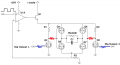
Hello guys. I've built a voltage controlled current sink. I'm using the basic op amp - transistor configuration, and so far it appears that it is working as expected. I'm applying a square wave at the op amp input to obtain current pulses.
The problem is I need to be able to invert the direction of the current at the load. For this reason, the first thing that came to mind is an H-Bridge. I've found a paper that used such configuration. However, the voltage/current levels are different.

The load is a 1k resistor with a small parallel capacitor (500pf). I need to provide 100mA pulses (max), so the load will see 100V max.
My questions are: Is this configuration a good approach to deliver the pulses in both directions? Are there any H bridge IC's that might fulfill such current/voltage requirements? If I need to build it myself, what other points do I need to consider for this approach.
Thanks a lot guys, any help is appreciated.
The problem is I need to be able to invert the direction of the current at the load. For this reason, the first thing that came to mind is an H-Bridge. I've found a paper that used such configuration. However, the voltage/current levels are different.
The load is a 1k resistor with a small parallel capacitor (500pf). I need to provide 100mA pulses (max), so the load will see 100V max.
My questions are: Is this configuration a good approach to deliver the pulses in both directions? Are there any H bridge IC's that might fulfill such current/voltage requirements? If I need to build it myself, what other points do I need to consider for this approach.
Thanks a lot guys, any help is appreciated.