Facebook
 Google
 GitHub
 Linkedin
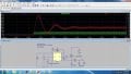
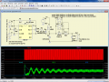
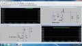
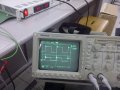
Ok, the LTSpice seems to be a good simulator and I've just downloaded it in hope to simulate my design before I starts asking anymore questions which could be explained using the software.No. The "camel hump" occurs AFTER the inductor is discharged and the diode ceases conducting. It's a result of the inductor and the output cap being series resonant. See the attached simulation; I stopped the gate signal after 58 pulses. The time frame I zeroed in on was right after the startup was complete.
It's due to the resonance of L1 and the output capacitor being in series.
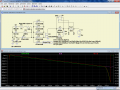
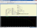
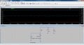
However when I run the simulation (transient analysis) in hope to see the charging voltage curve (which I should see the Vout = ~6.32V at 1s since R=1kΩ C=1mF), what I got is a single straight line which seems incorrect (see attached).
Do you know what went wrong?
Also, SgtWookie, did you download the Spice model of the IRF630N and IR2117 from IRF website directly? What I've found is only the PSpice model, are those compatible with LT Spice?
Thanks in advance.
Attachments
-
 239.7 KB Views: 66


")