 Facebook
 Google
 GitHub
 Linkedin
Hello,
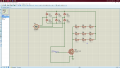
I am designing a High power dissipation board that consist of Parallel and Series connected Resistive load,I Considering the use of High Power IGBT Module to do so so as I can get a Linear Load curve using PWM Switching.
Input AC- 415
Topology- Star
O/P DC From Rectifier-560~600v
Load Power-30KW
I am designing a High power dissipation board that consist of Parallel and Series connected Resistive load,I Considering the use of High Power IGBT Module to do so so as I can get a Linear Load curve using PWM Switching.
Input AC- 415
Topology- Star
O/P DC From Rectifier-560~600v
Load Power-30KW
Attachments
-
 127.3 KB Views: 13


