They arn't the same. They have the same cut off frequency but different phase which indicate one phase is leading the voltage and the other is lagging . You should post an accompanying circuit to clarify the problem
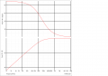
Typical high pass as your drawing would be as attached. At the low frequencies the capacitor is doing the most work (DC blocking). Its capacitive reactance acts as very high resistance with 90Deg leading phase of current with respect to voltage. As the frequency is increasing the capacitive reactance (frequency depedant resistance) reduces and so does the phase margin. At high frequency the capacitive reactance is next to nothing and it also has very little effect on phase.
It could be your lecturer is focussing on Voltage on his drawing so he is explaing the Voltage is lagging the current rather than the current is leading the voltage .
I think your lecturer is focussing on Voltage on his drawing so he is explaing that the Voltage is lagging the current rather than the current is leading the voltage its exactly the same but the context is different.
 Facebook
 Google
 GitHub
 Linkedin